Detailed Explanation of Fiber Optic Bend Losses
In modern optical communication systems, optical fibers serve as the core transmission medium, and their performance directly affects the stability and reliability of the network. Bend losses are a common source of loss in fiber optic deployments, especially in Fiber-to-the-Home (FTTH), data centers, and dense cabling scenarios, where excessive bending can lead to signal attenuation or even interruption. This article, based on the RP Photonics Encyclopedia and relevant industry standards and technical literature, provides a detailed analysis of the principles, influencing factors, calculation methods, and prevention measures of fiber optic bend losses, helping readers to gain a deeper understanding of this critical phenomenon.
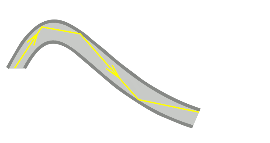
The image above shows the basic structure of an optical fiber and the principle of light transmission. When the optical fiber is bent, some light leaks into the cladding, resulting in bend loss.
I. What are Bend Losses?
Bend loss refers to the additional propagation loss caused by the bending of an optical fiber (or other waveguide). The main mechanism is the coupling of optical power from the guided mode (core mode) to the cladding modes, causing it to leak out of the core and preventing further transmission. Bend losses are divided into two types:
1. Macrobending Losses
Caused by macroscopic bending of the optical fiber. When the bending radius is smaller than a certain critical value, the loss increases sharply. Typical scenarios include corners and coiling during fiber optic cabling.
2. Microbending Losses
Caused by microscopic disturbances in the axial direction of the optical fiber, such as uneven coating, external pressure, or manufacturing defects. Even if the fiber is macroscopically straight, microbending can cause losses, usually related to temperature and pressure. In addition, bending can also cause a reduction in mode area (especially in large mode area fibers) and birefringence, affecting polarization characteristics.
II. Physical Mechanism of Bend Losses
Light is transmitted in an optical fiber by total internal reflection. When the optical fiber is bent, the optical path on the outer side of the bend becomes longer. To maintain wavefront phase consistency, some light “spills out” of the core and couples into the cladding modes. One commonly used explanation model is the Equivalent Index Method:
– A bent fiber can be considered equivalent to a straight fiber, but with a tilted refractive index distribution (higher effective refractive index on the outer side).
– The elasto-optic effect is included to correct for refractive index changes caused by mechanical stress.
– When the bend is too tight, the guided mode cannot be completely confined, leading to radiation loss.
In multimode fibers, higher-order modes are more easily affected; in single-mode fibers, longer wavelengths (with larger mode expansion) are more sensitive. The loss may also exhibit **oscillatory characteristics** due to interference from reflections at the cladding/coating boundary. Simulations (such as those for large mode area fiber bending) show that as the bend increases, the mode shifts towards the inner side of the bend, its area decreases, and optical power leaks into the cladding.
III. Key Factors Affecting Bending Loss
Bending loss is affected by several parameters:
1. Bend Radius: A critical radius exists: loss is negligible above the critical value, but increases exponentially below it.
– High numerical aperture (NA) fibers: Critical radius is only a few millimeters.
– Large mode area single-mode fibers: Critical radius can reach tens of centimeters.
2. Wavelength: Longer wavelengths experience greater loss (e.g., 1550nm is more sensitive than 1310nm) because longer wavelength modes are less confined. This limits the effective operating wavelength range of the fiber.
3. Fiber Parameters:
Numerical Aperture (NA): Higher NA results in stronger resistance to bending (smaller critical radius).
Mode Type: Higher-order modes in multimode fibers are more susceptible to loss, which can be used for mode filtering; single-mode fibers generally have a larger critical radius.
Mode Field Diameter/Effective Mode Area: Large mode area fibers experience significant mode deformation when bent. 4. Other: Micro-bending is related to external mechanical pressure; in integrated photonic circuits, small radius bends (micrometer scale) require high NA waveguides.
IV. Calculation Methods for Bending Loss
Accurate calculation requires numerical simulation (such as ray tracing or beam propagation method, supported by RP Fiber Power software).
Common approximation methods include:
1. Equivalent Refractive Index Model: The bend is equivalent to a refractive index gradient, and the mode distribution and loss are calculated.
2. Classic Marcuse formula (proposed in 1976, with subsequent improvements): For single-mode fiber, the macro-bending loss coefficient α (dB/m) is approximately in exponential form: α ∝ exp(−R / R₀)
Where R is the bending radius, and R₀ is related to the wavelength, the core/cladding refractive index difference, and the mode field diameter. More precise versions involve Bessel functions and normalized frequency V. In practical engineering, empirical values are often given through OTDR measurements or reference standards (such as ITU-T G.652/G.657).
V. Typical Values and Industry Standards
Standard single-mode fiber (G.652): Recommended minimum bending radius is approximately 30mm; too small a radius will lead to several dB of loss (especially at 1625nm wavelength).
Bend-insensitive fiber (G.657):
– G.657.A1/A2: Compatible with G.652, minimum radius 15mm~7.5mm.
– G.657.B3: Ultra-bend resistant, minimum radius 5mm, suitable for dense wiring. These fibers have extremely low loss at small radii (<0.1dB/turn).
Typical application: In FTTH, G.657 fibers allow for compact fiber coiling without significantly increasing loss.
Comments are closed