Full Analysis of 1×2 Magneto-Optic Switch Optical Path: A Systematic Overview from Structural Composition to Optical Path Switching Algorithm
In high-speed optical communication and optical networks, optical switches are key devices for flexible signal routing. The 1×2 magneto-optic switch (MOS) is a typical type, featuring fast switching, low insertion loss, and high reliability. This article provides a systematic analysis of its structural composition, working principle, and optical path switching mechanism.
1. Basic Concept of 1×2 Magneto-Optic Switch
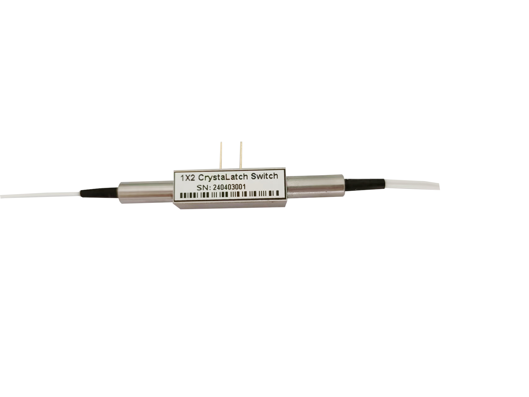
1×2 magneto-optic switch has one input port and two output ports. Its core function is to selectively transmit the input optical signal to either output port under the control of an external magnetic field. Compared with mechanical or MEMS switches, magneto-optic switches have no moving parts, offering fast switching speed, long lifetime, and stable performance under high-power conditions.
2. Structural Composition
The typical structure of a 1×2 magneto-optic switch includes:
-
Input and Output Fiber Interfaces
-
The optical signal enters through the input fiber and exits through output fibers.
-
Common connector types include FC/APC and LC/PC to ensure low insertion loss and high stability.
-
-
Magneto-Optic Material Layer
-
The core functional unit, usually made of materials such as bismuth-doped yttrium iron garnet (Bi:YIG).
-
The Faraday effect in this material rotates the polarization of light, enabling control of the optical path.
-
-
Waveguide Structure
-
Typically made of doped silica or photonic crystal waveguides.
-
The waveguide ensures sufficient interaction of light with the magneto-optic material and maintains mode matching to minimize loss.
-
-
Magnetic Coil or Permanent Magnet
-
External current or magnetic field controls the magnetization direction of the magneto-optic material.
-
The magnetic field determines the polarization rotation of light, which selects the output port.
-
-
Polarizing Beam Splitter or Optical Coupler
-
Separates light of different polarization states into different output ports.
-
Can be implemented with a polarizing beam splitter (PBS) or waveguide-based routing structure.
-
3. Optical Path Principle
The core principle of the magneto-optic switch is the Faraday Effect:
-
Light enters the waveguide and passes through the magneto-optic material.
-
Under the applied magnetic field, the material rotates the polarization of the light. The rotation angle is proportional to the magnetic field strength.
-
A polarizing beam splitter or waveguide structure guides light with different polarization states to different output ports, achieving optical path switching.
In short, switching relies on two steps:
-
Polarization Rotation: The magneto-optic material rotates the light’s polarization under the magnetic field.
-
Polarization-Based Routing: The rotated polarization determines which output port receives the light.
4. Optical Path Switching Algorithm and Control Mechanism
The control of a 1×2 magneto-optic switch centers on external magnetic field adjustment. The main steps include:
-
Magnetic Field Calculation
-
Calculate the required magnetic field based on input power and output requirements.
-
The Faraday rotation angle formula is used:
θ=V⋅B⋅L\theta = V \cdot B \cdot L
where VV is the Verdet constant, BB is the magnetic field strength, and LL is the length of the light path in the magneto-optic material.
-
-
Current Drive Optimization
-
For coil-driven switches, the current is precisely adjusted to achieve the desired magnetic field.
-
Closed-loop control ensures stable switching performance.
-
-
Output State Determination
-
Optical power feedback monitors whether the light reaches the target output port accurately.
-
Deviations trigger automatic adjustment of the magnetic field or polarization control parameters.
-
-
Switching Timing Control
-
Switching times range from nanoseconds to microseconds.
-
The control system allows rapid routing for dynamic optical network scheduling.
-
5. Performance Advantages and Applications
Performance Advantages:
-
High-Speed Switching: Nanosecond-to-microsecond response.
-
No Mechanical Wear: Long lifetime and high reliability.
-
Low Insertion Loss & High Return Loss: Suitable for precise optical networks.
-
High Power Handling: Compatible with high-power optical paths and laser applications.
Application Scenarios:
-
Dynamic routing in optical fiber networks
-
Optical signal distribution and switching systems
-
High-power laser optical path control
-
Rapid optical path switching in research and laboratory settings
6. Conclusion
The 1×2 magneto-optic switch achieves rapid optical path switching through a combination of magneto-optic materials, waveguide structures, and magnetic field control. Its core mechanism uses Faraday-effect-induced polarization rotation followed by polarization-based routing to select the output port. With advanced control algorithms and feedback systems, magneto-optic switches play a critical role in high-speed, precision optical networks. Future advancements in material science and optical design will further expand their applications to higher bandwidths and multi-port networks.
Comments are closed