Fused Buccinate Tapered Optical Splitter
An optical fiber splitter, also known as a splitter, is a passive optical device that separates a single optical fiber signal into two or more output optical signals according to a predetermined ratio. It is used for FTTH (Fiber to the Home) connections. For example, a 1×4 optical splitter distributes the optical signal from one optical fiber to four optical fibers according to a specific ratio. Unlike WDM systems where wavelength division multiplexers and demultiplexers separate optical signals of different wavelengths into corresponding wavelength channels, optical splitters distribute the entire optical signal across multiple channels for transmission.
I. Working Principle of Optical Splitters
When transmitting optical signals in single-mode fiber, the energy of the light is not entirely concentrated in the fiber core; a small amount propagates through the cladding near the core. In other words, if the cores of two fibers are close enough, the mode field of the light propagating in one fiber can enter the other, resulting in a redistribution of the optical signal between the two fibers.

II. Types of Optical Splitters
Optical splitters can be classified into two types based on their operating principle: planar waveguide (PLC) optical splitters and fused biconical taper (FBT) optical splitters. Based on port configuration, they can be classified as: X-type (2×2) couplers, Y-type (1×2) couplers, and star-type (NxN, N…) couplers. >2) Couplers, tree-type (1xN, N>2) couplers, etc.; according to the splitting ratio, they can be divided into non-uniform and uniform splitting; another classification method is by single-mode (1310nm) and multi-mode (850nm).
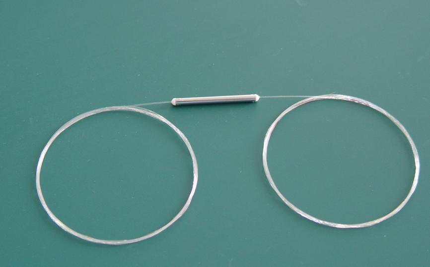
1. FBT Fused Tapered Optical Splitter
The FBT optical splitter is manufactured using the traditional tapered coupler process. Two or more optical fibers with the coating removed are bundled together, then heated and melted at high temperature on a tapering machine, while being stretched to both sides. The change in the splitting ratio is monitored in real time. Once the splitting ratio reaches the required level, the melting and stretching process ends. One end retains one fiber (the rest are cut off) as the input end, and the other end serves as the multi-output end. Different splitting ratios can be obtained by controlling the angle of fiber twisting and the length of stretching. Finally, the tapered area is cured with adhesive onto a quartz substrate and inserted into a stainless steel tube.
2. PLC Planar Waveguide Optical Splitter
PLC (Planar Waveguide) A Lightwave Circuit (PLC) optical splitter is an integrated waveguide optical power distribution device based on a quartz substrate, fabricated using semiconductor processes (photolithography, etching, development, etc.). The PLC splitter splits an optical signal from one optical fiber into multiple optical fibers, achieving uniform distribution of optical energy. The optical waveguide array is located on the upper surface of the chip, integrating the splitting function onto the chip; then, multi-channel fiber arrays are coupled to the input and output ends at both ends of the chip and packaged.
3. FBT VS The main advantages of PLC
FBT tapered splitters are simple raw material usage, relatively low cost, and less demanding equipment and process requirements. The splitting ratio can be monitored in real-time as needed, allowing for the fabrication of unequal splitters. The disadvantages are: currently, mature tapering technology can only produce splitters up to 1×4. For devices larger than 1×4, multiple 1×2 units are connected together and then packaged in a splitter housing. FBT splitters only support three wavelengths: 850nm, 1310nm, and 1550nm, making them incompatible with other wavelengths.
The product characteristics of PLC splitters are: losses are insensitive to optical wavelength, meeting the transmission requirements of different wavelengths (1260~1650nm); and uniform beam splitting, ensuring even signal distribution. Assigned to users; compact structure and small size; high number of splitting channels per device, up to 64 or more: low cost per channel, the more channels, the more obvious the cost advantage. The disadvantage is that it is more expensive than fused biconical tapered splitters, especially in low-channel splitters.
III. Structure of PLC Optical Splitter
The PLC optical splitter consists of three parts: an optical splitter chip and fiber arrays coupled at both ends. These three components must be precisely aligned, and their design and assembly play a crucial role in the stability of the PLC splitter. The chip uses semiconductor technology to grow a layer of optical waveguide on a quartz substrate. The chip has one input end and N output waveguides. Then, input and output optical waves are coupled to both ends of the chip. A fiber array, enclosed in a housing, forms an optical splitter with one input and N outputs.
PLC splitter chips can be designed as 1xN and 2xN, where N is usually a multiple of 2, such as 1×2, 1×4, 1×8, 1×16, 1×32, 1×64; and non-uniformly distributed splitters, such as 1×3, 1×5, 1×9, etc. With the rise of FTTR (Fiber to the Room) demand, the application of non-uniformly distributed power splitters will become increasingly widespread, and the manufacturing process will become more challenging. PLC optical splitter chips have advantages such as low cost, high reliability, high flexibility, and scalability, making them particularly suitable for various application scenarios such as transmission systems, network integration, broadband access, fiber optic communication, and multimedia services.
1. Polarization-Maintaining PLC Splitter
Polarization-Maintaining PLC Splitter LC splitters primarily achieve uniform power splitting while maintaining polarization. A single-channel polarization-maintaining fiber array serves as the input, and a multi-channel polarization-maintaining fiber array serves as the output. The polarization of the linear polarized light wave emitted into the fiber remains unchanged during propagation, with minimal or no cross-coupling between polarization modes, thus achieving polarization-maintaining coupling and beam splitting. Typically, PANDA fiber is used. PLC optical splitters are mainly used in special applications requiring polarization maintenance, such as fiber optic sensing systems or coherent communication.
2. Key Parameters of PLC Optical Splitters
The performance parameters affecting optical splitters generally include the following:
- Insertion Loss Insertion loss (lL) refers to the reduction in optical power at a specified output port relative to the total input optical power at the operating wavelength of a PLC splitter. Simply put, it’s the dB loss of each output relative to the input. Generally, the lower the insertion loss, the better the splitter’s performance.
- Return loss (lL) refers to the ratio in decibels of the reflected light (scattered light continuously transmitted to the input) to the input light at the fiber optic connection. Higher return loss is better to reduce the impact of reflected light on the light source and system.
- Directivity refers to the ratio of the output optical power at the non-injection light end to the injected light power (measured wavelength) on the same side of the PLC splitter during normal operation.
- Polarization-dependent loss refers to the maximum change in output optical power at each output port of the PLC splitter when the polarization state of the transmitted optical signal changes across all polarization states.
- Isolation refers to the ability of a fiber optic splitter to isolate optical signals in other optical paths from a given optical path.
Comments are closed