Why Is the Extinction Ratio of Polarization-Maintaining Fiber So Difficult to Measure Accurately?
In the development, production, and testing of polarization-maintaining fiber (PM fiber), the extinction ratio (ER) is one of the most critical performance indicators.
However, many engineers encounter the same issue:
Why does the extinction ratio of the same PM fiber or device vary so much when measured by different instruments, operators, or at different times?
For example:
- A laboratory may measure 28 dB,
- while the customer site only gets 20 dB.
Or:
- A test report claims 30 dB,
- but the actual polarization performance in the optical system is unstable.
So why is the extinction ratio of PM fiber always “hard to measure accurately”?
This article analyzes the problem from the perspectives of polarization principles, testing methods, environmental influences, and practical engineering experience.
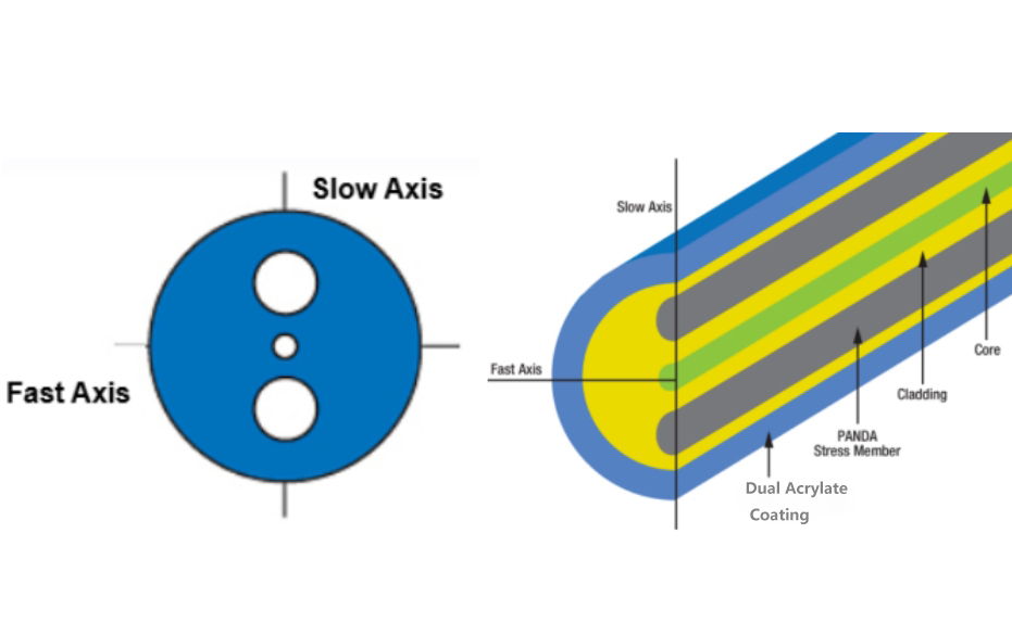
1. What Is the Extinction Ratio of PM Fiber?
The primary function of polarization-maintaining fiber is to preserve light propagation along a fixed polarization axis.
Ideally:
- Light propagates only along the slow axis,
- with almost no power coupled into the fast axis.
In reality:
- A portion of the optical power always couples into the orthogonal axis,
- reducing polarization purity.
Therefore, the extinction ratio is introduced to evaluate polarization performance.
The extinction ratio is commonly defined as:
ER(dB)=10log10(PmainPorthogonal)ER(dB)=10\log_{10}\left(\frac{P_{main}}{P_{orthogonal}}\right)
Where:
- PmainP_{main}: optical power in the principal polarization axis
- PorthogonalP_{orthogonal}: optical power in the orthogonal polarization axis
The higher the ER value:
- the better the polarization-maintaining performance,
- and the lower the polarization crosstalk.
For example:
| Extinction Ratio | Polarization Performance |
|---|---|
| 10 dB | Poor |
| 20 dB | Standard telecom grade |
| 25 dB | Good |
| 30 dB+ | High-performance laboratory grade |
2. Why Is Extinction Ratio So Difficult to Measure?
Unlike ordinary insertion loss testing, extinction ratio measurement is essentially:
A polarization-state measurement.
Polarization states are extremely sensitive.
Even tiny disturbances can cause several dB of fluctuation.
3. Six Major Reasons Why Extinction Ratio Measurements Are Inaccurate
1. The Input Polarization Is Not Perfectly Aligned with the Slow Axis
This is the most common issue.
Theoretically:
- The input light must be precisely aligned with the slow axis of the PM fiber.
Otherwise:
- Light enters both the slow and fast axes simultaneously,
- directly reducing the measured ER.
In practical applications:
- Inaccurate polarization controller adjustment,
- imperfect laser polarization purity,
- coupling angle deviation,
all contribute to measurement errors.
For example:
- An alignment error of only 1°
- may reduce the extinction ratio by several dB.
Therefore:
The input polarization purity often determines the upper limit of the measured ER.
2. Slight Fiber Bending Causes Polarization Crosstalk
PM fiber is highly sensitive to:
- Compression,
- twisting,
- bending,
- stretching.
Because these stresses alter the birefringence characteristics of the fiber.
As a result:
- Light propagating along the slow axis
- partially couples into the fast axis.
This phenomenon is known as:
Polarization Crosstalk
In many laboratories:
- Simply touching the fiber during testing
- may change the ER by 2–5 dB.
Especially for:
- Panda PM fiber,
- Bow-tie PM fiber,
which are highly sensitive to mechanical stress.
Therefore, during high-precision testing:
- Fibers should lie naturally,
- without tension,
- without sharp bends,
- and without suspension stress.
3. Connector Key Angle Errors
PM fiber connectors such as FC/APC use:
- Key-keyway alignment structures.
Ideally:
- The connector key corresponds exactly to the slow axis orientation.
In reality:
- Connector assembly always has angular tolerances,
- commonly around ±1° to ±3°.
This directly impacts extinction ratio performance.
For example:
| Angular Error | Theoretical ER Limit |
|---|---|
| 1° | ~35 dB |
| 2° | ~29 dB |
| 3° | ~25 dB |
| 5° | ~21 dB |
Therefore:
In many cases, the problem is not the fiber itself, but insufficient connector alignment accuracy.
High-end PM devices typically require:
- Key error ≤ 0.5°
4. The Test Equipment Itself Can Introduce Errors
1. Polarization Analyzer Limitations
Different instruments have different:
- Dynamic ranges,
- polarization resolution capabilities.
For example:
- Some standard analyzers can only accurately measure up to 25 dB.
- Beyond that, readings may drift significantly.
Thus:
The instrument limit is often mistaken for the actual device performance.
2. Poor Light Source Stability
If the laser source suffers from:
- Polarization drift,
- power fluctuation,
- mode hopping,
the measured ER will continuously vary.
This is especially common with:
- DFB lasers during thermal changes,
- broadband ASE sources,
- multimode lasers.
3. Wavelength Dependence of Birefringence
The birefringence characteristics of PM fiber are wavelength dependent.
Therefore:
- 1310 nm,
- 1550 nm,
- 1064 nm,
may produce different ER results for the same device.
Even within the C-band:
- ER can vary noticeably across wavelengths.
5. Many “High ER” Results Are Actually Misleading
A very common industry phenomenon is:
“Short-Fiber High-ER Effect”
For example:
- A 10 cm PM fiber
- can easily measure above 35 dB.
However:
- At 5 meters,
- the ER may drop to only 20 dB.
The reason is:
- Accumulated polarization crosstalk,
- cumulative environmental stress disturbances.
Therefore:
Short-fiber test results do not necessarily represent real system performance.
6. Why Are Customer-Site Results Often Different from Laboratory Results?
This is one of the most common engineering challenges.
In laboratories:
- Temperature is stable,
- fibers are fixed,
- vibration is minimal.
At customer sites:
- Cooling fans,
- cable drag chains,
- mechanical vibration,
- temperature fluctuations,
all affect polarization stability.
As a result:
- Polarization states continuously change,
- and extinction ratio fluctuates constantly.
This is especially critical in:
- Fiber optic gyroscopes,
- coherent communication systems,
- interferometric systems,
- fiber lasers.
7. How to Properly Measure PM Fiber Extinction Ratio
1. Use a High-Polarization-Purity Light Source
Recommended:
- Laser sources with PER > 30 dB,
- stable single-frequency lasers.
Avoid:
- Multimode light sources,
- randomly polarized sources.
2. Precisely Align the Slow Axis
Recommended methods:
- Use a polarization controller,
- combined with a real-time polarization analyzer.
Goal:
- Ensure the input polarization is perfectly aligned with the PM axis.
3. Avoid Any Mechanical Disturbance During Testing
The fiber must:
- Lie naturally,
- remain unstressed,
- avoid compression,
- avoid pulling forces.
This is often overlooked in practical testing.
4. Control Environmental Temperature
For high-precision measurements:
- Use a temperature-controlled environment,
- avoid direct airflow,
- minimize thermal drift.
5. Do Not Focus Only on a Single ER Reading
A better approach is:
- Continuous monitoring,
- dynamic recording over time.
Because:
Truly excellent PM devices are not defined by the highest peak ER, but by ER stability.
8. How to Improve the Real Extinction Ratio of PM Devices
Besides testing methods, device design and manufacturing are equally important.
Key factors include:
1. High-Precision Axis Alignment
For example:
- Active V-groove alignment,
- six-axis alignment platforms,
- submicron positioning.
2. Low-Stress Packaging
Packaging must minimize:
- Thermal stress,
- adhesive shrinkage,
- metal compression stress.
Otherwise:
- ER may significantly degrade after packaging.
3. Use High-Birefringence PM Fiber
Examples include:
- Panda fiber,
- Bow-tie fiber.
Higher birefringence provides:
- Better resistance to environmental disturbances.
4. Optimize Fusion Splicing Quality
The most important factor in PM fiber splicing is:
- Accurate axis alignment.
Standard single-mode fusion splicing methods are not suitable for PM fibers.
9. Conclusion
The reason PM fiber extinction ratio is “difficult to measure accurately” is not simply due to testing instruments, but because:
Polarization states are inherently extremely sensitive.
Any small change in:
- Alignment angle,
- mechanical stress,
- temperature,
- or source stability
can significantly affect the final ER result.
Therefore:
Extinction ratio is never an absolutely fixed value.
Instead:
It is a dynamic parameter highly dependent on testing conditions, environmental factors, and device manufacturing quality.
For high-end PM devices:
What truly matters is not:
- the highest ER achievable in a laboratory,
but rather:
- long-term stability,
- environmental robustness,
- and real-world polarization-maintaining performance.
These are the factors that truly determine the quality of PM optical devices.
Comments are closed