Fiber Network Testing and Monitoring: Why Choose a 1×N Rackmount Optical Switch?
As fiber optic networks continue to expand in scale and complexity, ensuring reliable performance and efficient maintenance has become more critical than ever. For telecom operators, data centers, and research institutions, automated fiber testing and monitoring is no longer optional—it’s essential.
Among the available solutions, the 1×N rackmount optical switch stands out as a key component for building efficient, scalable, and cost-effective testing systems.
What Is a 1×N Rackmount Optical Switch?
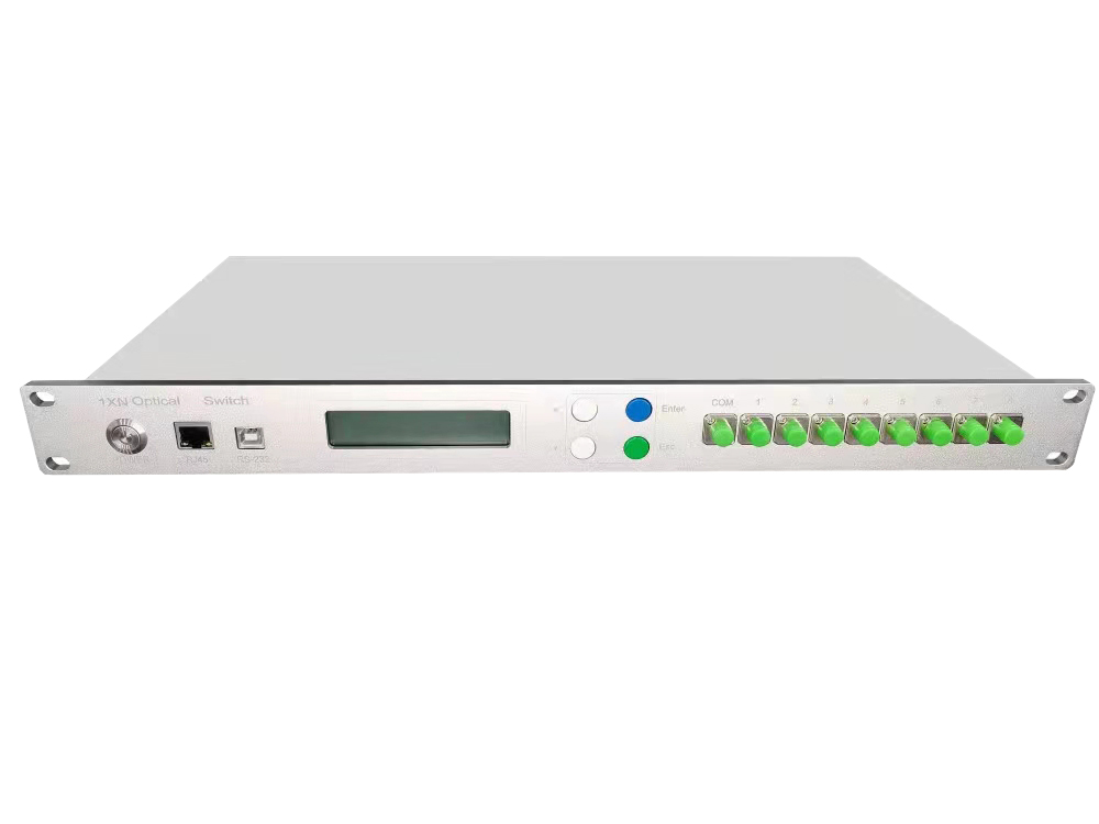
A 1×N optical switch allows a single input optical signal to be routed to multiple output channels (such as 1×2, 1×8, 1×16, or 1×32). The rackmount design enables easy integration into standard 19-inch cabinets, making it ideal for centralized network management.
It functions as an intelligent optical path selector, enabling multiple fiber links to share a single test instrument.
Challenges in Fiber Network Testing
Modern fiber networks face several operational challenges:
- High cost of test equipment (e.g., OTDR, optical power meters)
- Large number of distributed fiber links
- Manual testing is time-consuming and error-prone
- Risk of service disruption during testing
These challenges highlight the need for an automated optical switching solution.
Key Benefits of 1×N Rackmount Optical Switches
1. Automated Testing and Remote Control
With support for RS232, USB, and RJ45 (Ethernet) interfaces, rackmount optical switches enable seamless remote operation and automated test sequences. They can be easily integrated into network management systems (NMS) for centralized control.
2. Reduced Equipment Cost
Instead of deploying multiple test devices, a single OTDR can be shared across multiple fiber channels via the optical switch, significantly reducing capital expenditure.
3. Minimal Service Interruption
High-performance optical switches offer low insertion loss and high isolation, allowing near real-time monitoring with minimal impact on live traffic.
4. Centralized Rackmount Design
The rackmount structure provides:
- Organized cable management
- Unified power supply
- Easy integration into existing racks
- Remote monitoring and control
5. Scalable and Flexible Configuration
Available in multiple channel configurations (1×8, 1×16, 1×32, etc.), these switches can be easily scaled to meet growing network demands.
Typical Applications
OTDR Automated Testing Systems
Enable scheduled and automated testing of multiple fiber links using a single OTDR device.
Data Center Fiber Monitoring
Continuously monitor critical fiber connections to ensure high availability and rapid fault detection.
Production and Laboratory Testing
Improve testing efficiency in fiber optic component manufacturing and R&D environments.
How to Choose the Right Optical Switch
When selecting a 1×N rackmount optical switch, consider the following parameters:
- Insertion Loss – Lower is better
- Return Loss – Important for signal quality
- Crosstalk / Isolation – Higher ensures stability
- Switching Time – Impacts testing efficiency
- Control Interface – RS232 / USB / RJ45 (Ethernet)
- Fiber Type – Single-mode (SM), Multimode (MM), Polarization Maintaining (PM)
Conclusion
As fiber networks evolve, traditional manual testing methods are no longer sufficient. The 1×N rackmount optical switch provides a smart, scalable, and cost-efficient solution for modern fiber network testing and monitoring.
By enabling automation, reducing costs, and improving operational efficiency, it has become an essential component in next-generation optical network management systems.
Comments are closed