


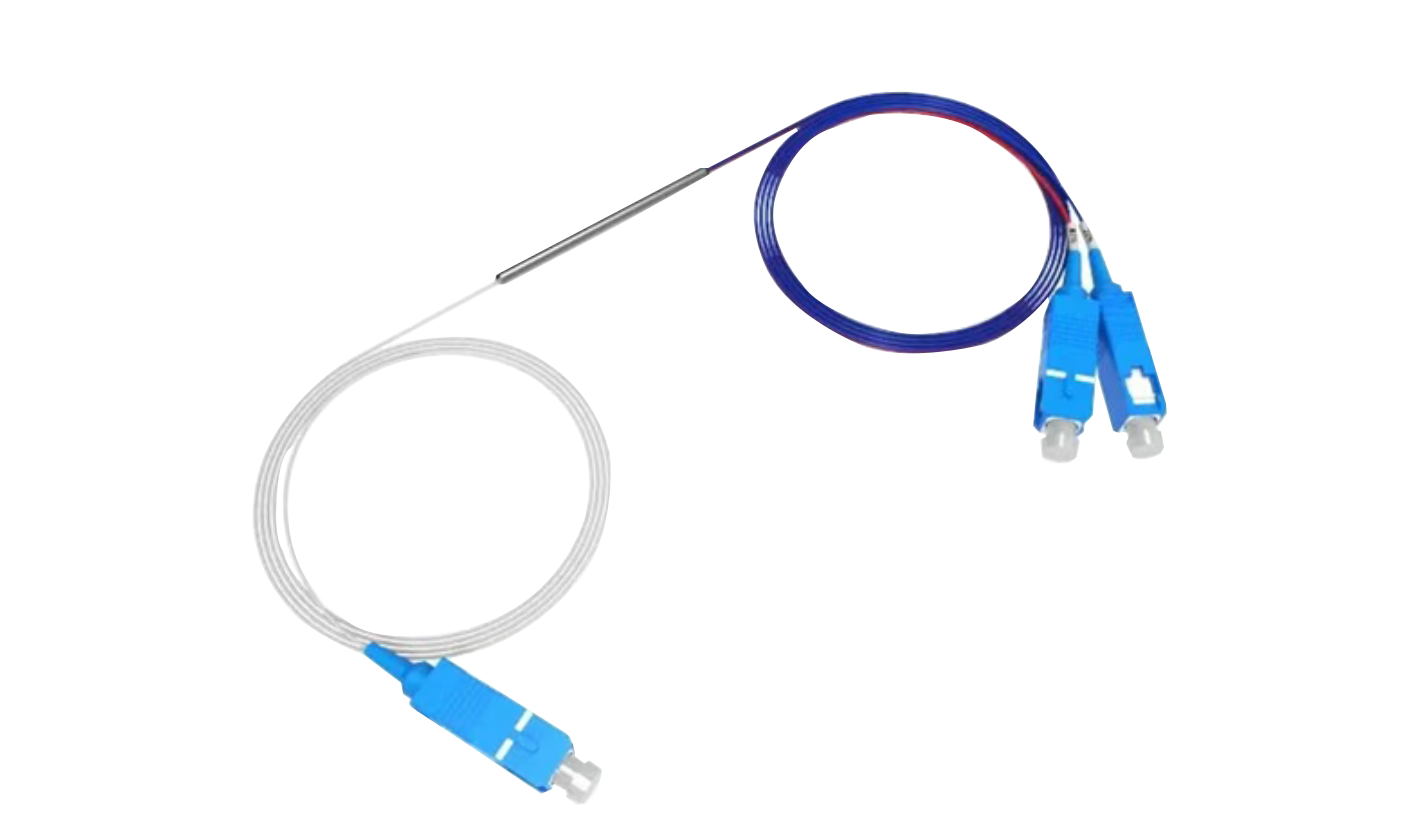
PM Fiber Coupler Wavelength and Coupling Ratio: A Selection Guide from 780nm to 1550nm
In fiber optic communication, fiber sensing, fiber lasers, fiber gyroscopes, and research systems, Polarization Maintaining (PM) Fiber Couplers are used to split optical power between different output ports while maintaining the polarization state of the transmitted light.
When selecting a PM fiber coupler, two of the most important parameters are the operating wavelength and coupling ratio. Different applications require different combinations of these parameters, so choosing the right PM coupler can directly affect optical power distribution, polarization stability, and overall system performance.
This guide explains common PM fiber coupler wavelengths from 780nm to 1550nm and how to select the appropriate coupling ratio for different applications.
1. What Is a PM Fiber Coupler?
A PM fiber coupler is a passive optical device designed to divide or combine optical signals while maintaining their polarization state.
Compared with standard single-mode fiber couplers, PM fiber couplers typically use polarization-maintaining fibers with high birefringence. This structure helps reduce polarization changes caused by environmental factors such as temperature, vibration, and mechanical stress.
When selecting a PM fiber coupler, the key specifications normally include:
- Operating Wavelength
- Coupling Ratio
- Polarization Extinction Ratio (PER)
- Insertion Loss (IL)
- Excess Loss
- Return Loss (RL)
- Fiber Type
- Connector Type
- Optical Power Handling
PM fiber couplers are available for a wide range of wavelengths, including 780nm, 850nm, 980nm, 1064nm, 1310nm, 1480nm, and 1550nm.
2. How to Select the Operating Wavelength from 780nm to 1550nm?
The operating wavelength should first be selected according to the wavelength of the laser source or optical system.
780nm PM Fiber Coupler
780nm is a commonly used wavelength in the near-infrared range.
Typical applications include:
- Fiber optic sensing
- Atomic physics experiments
- Laser measurement
- Optical experiments
- Research instruments
For 780nm applications, a PM780-type fiber is generally selected to match the operating wavelength.
If the laser source operates around 780nm, it is recommended to select a PM fiber coupler specifically designed for this wavelength rather than choosing a general-purpose coupler simply based on a broad wavelength range.
850nm PM Fiber Coupler
850nm is widely used in optical communication and near-infrared optical systems.
Typical applications include:
- 850nm fiber optic communication
- Fiber optic sensing
- VCSEL systems
- Laboratory optical systems
- Polarization measurement
When selecting an 850nm PM coupler, the fiber type, polarization extinction ratio, insertion loss, and coupling ratio should be considered together.
980nm PM Fiber Coupler
980nm PM fiber couplers are commonly used in:
- EDFA pump systems
- Fiber amplifiers
- Fiber lasers
- Fiber optic sensing
For 980nm applications, optical power handling is particularly important.
If the PM coupler is used in a pump path, make sure that the device can safely handle the actual input power of the system.
1064nm PM Fiber Coupler
1064nm is an important wavelength for fiber lasers, solid-state lasers, scientific research, and optical measurement systems.
Typical applications include:
- 1064nm fiber lasers
- Laser measurement
- Interferometric systems
- Fiber optic sensing
- Scientific research
For 1064nm systems that require both high optical power and stable polarization, the selection should consider:
Wavelength + Coupling Ratio + PER + Optical Power Handling
rather than focusing only on the coupling ratio.
1310nm PM Fiber Coupler
1310nm is a classic wavelength for fiber optic communication and is also widely used in sensing and optical testing systems.
Typical applications include:
- Fiber optic communication
- Optical network testing
- Fiber optic sensors
- Interferometers
- Optical instruments
For 1310nm systems, different coupling ratios such as 50:50, 90:10, or 99:1 can be selected according to the required optical power distribution.
1480nm PM Fiber Coupler
1480nm is commonly associated with fiber amplifiers, pump systems, and specific fiber laser applications.
For applications such as EDFA pump systems, important parameters include:
- Pump wavelength
- Pump power
- Coupling ratio
- Insertion loss
- Return loss
- Polarization extinction ratio
The appropriate PM fiber type and optical power rating should be selected according to the actual system requirements.
1550nm PM Fiber Coupler
1550nm is one of the most widely used wavelengths in fiber optic communication and optical fiber systems.
Typical applications include:
- Optical communication
- Fiber optic sensors
- Fiber lasers
- Optical amplifiers
- Interferometric systems
- Fiber optic gyroscopes
1550nm PM couplers are available with a variety of coupling ratios, including 50:50, 75:25, 90:10, and 99:1.
For 1550nm systems, engineers can select the appropriate ratio according to signal splitting, power monitoring, and system feedback requirements.
3. How to Select the Coupling Ratio?
After determining the operating wavelength, the next important parameter is the coupling ratio.
Common coupling ratios include:
| Coupling Ratio | Typical Application |
|---|---|
| 50:50 | Equal power splitting, interferometers |
| 60:40 | Unequal power distribution |
| 70:30 | Main path + auxiliary path |
| 80:20 | Main signal + monitoring |
| 90:10 | Optical power monitoring |
| 95:5 | Low-power monitoring |
| 98:2 | Low-level optical monitoring |
| 99:1 | High-power signal monitoring |
The available coupling ratios depend on the PM coupler design and manufacturer.
4. When Should You Use a 50:50 PM Coupler?
The 50:50 coupling ratio is one of the most common choices for PM fiber couplers.
Ideally, an input optical signal is divided equally between the two output ports.
For example, if the input power is 100mW, approximately 50mW will be directed to each output under ideal conditions.
50:50 PM couplers are commonly used in:
- Interferometers
- Fiber optic sensors
- Optical testing systems
- Balanced optical systems
- Laboratory research
However, the actual output power will also be affected by insertion loss, excess loss, and coupling-ratio tolerance. Therefore, a practical 50:50 coupler does not necessarily provide exactly 50mW at each output.
5. Why Are 90:10 and 99:1 Couplers Suitable for Optical Power Monitoring?
If most of the optical power needs to remain in the main optical path while only a small portion is required for monitoring, a 90:10, 95:5, 98:2, or 99:1 coupler can be a better choice.
For example:
90:10 Coupler
Approximately 90% of the optical power is directed to the main output, while approximately 10% is used for monitoring.
99:1 Coupler
Approximately 99% of the optical power remains in the main optical path, while approximately 1% is tapped for monitoring.
These coupling ratios are particularly useful for:
- Optical power monitoring
- Laser monitoring
- Fiber amplifier monitoring
- Feedback systems
- Optical test equipment
Therefore, if the requirement is to maintain maximum power in the main signal path while taking a small optical sample for monitoring, a low-ratio tap coupler is generally more suitable than a 50:50 coupler.
6. Does a Lower Coupling Ratio Mean a Lower PER Requirement?
This is an important consideration when selecting a PM fiber coupler.
For low-ratio tap ports, such as 1% or 2%, the optical power at the monitoring port is much lower than that of a 50:50 coupler. The PER specification and measurement conditions may therefore differ between the main and tap ports.
If a system requires both a specific coupling ratio and high polarization stability, the PER requirement should be clearly specified.
For example, instead of simply requesting:
99:1 PM Coupler
it is better to specify:
99:1 coupling ratio with a specified polarization extinction ratio.
This helps ensure that the final product meets the actual system requirements.
7. PM Fiber Coupler Selection: Parameters Beyond Wavelength and Coupling Ratio
Although wavelength and coupling ratio are two key specifications, a complete PM fiber coupler selection should also consider the following parameters.
① Polarization Extinction Ratio
PER is an important parameter for evaluating the polarization-maintaining performance of an optical component.
For systems with strict polarization stability requirements, the required PER should be clearly specified rather than simply stating that the product uses PM fiber.
② Insertion Loss
Insertion loss directly affects the optical power available to the system.
For low coupling ratios such as 99:1, it is especially important to understand the insertion loss of both the main output and tap output.
③ Excess Loss
Excess loss represents the additional optical loss introduced by the coupling process and is an important indicator of coupler efficiency.
④ Fiber Type
Different wavelengths normally require different types of PM fiber, such as:
- PM780
- PM850
- PM980
- PM1310
- PM1550
The fiber type should match the operating wavelength and system requirements.
⑤ Connector Type
Common connector options include:
- FC/PC
- FC/APC
- SC/PC
- SC/APC
- LC/UPC
- LC/APC
For systems that are sensitive to optical reflection, connector type should be carefully considered.
It is also important to confirm whether the specified IL, RL, and PER values apply to the bare-fiber device or the connectorized assembly.
8. Quick PM Fiber Coupler Selection Guide: 780nm to 1550nm
| Operating Wavelength | Typical Applications | Key Considerations |
|---|---|---|
| 780nm | Sensing, research, laser measurement | Wavelength range, PER |
| 850nm | Communication, VCSEL, sensing | Fiber type, PER |
| 980nm | Fiber amplifiers, pump systems | Optical power handling |
| 1064nm | Fiber lasers, research | High power, PER |
| 1310nm | Optical communication, sensing | IL, coupling ratio |
| 1480nm | Fiber amplifiers, pump systems | Power, optical loss |
| 1550nm | Communication, lasers, sensing | PER, coupling ratio, bandwidth |
9. How to Quickly Select the Right PM Fiber Coupler?
A practical selection process can follow these steps.
Step 1: Determine the Laser Wavelength
For example:
Laser wavelength = 1550nm
Select a PM fiber coupler designed for 1550nm operation.
Step 2: Determine the Required Power Distribution
For approximately equal power distribution:
50:50
For a main signal and monitoring path:
90:10 / 95:5
For a very small monitoring signal:
98:2 / 99:1
Step 3: Define the Polarization Requirement
If the system requires high polarization stability, specify the required PER:
PER ≥ XX dB
Step 4: Confirm the Optical Power
For example:
Input Power = 500mW / 1W / 2W / Higher
For high-power applications, confirm the actual power-handling capability with the manufacturer rather than selecting a standard communication-grade coupler.
Step 5: Confirm the Fiber and Connector
Finally, specify:
Fiber Type + Fiber Length + Connector + Package
This provides a complete specification for PM fiber coupler selection.
Conclusion
When selecting a PM Fiber Coupler, the operating wavelength determines whether the coupler matches the optical source, while the coupling ratio determines how optical power is distributed between the output ports.
From 780nm to 1550nm, different wavelengths are used in different laser, communication, sensing, and research applications. A 50:50 PM coupler is suitable for equal power splitting and interferometric systems, while 90:10, 95:5, 98:2, and 99:1 couplers are often more suitable for optical power monitoring and signal tapping.
Therefore, when purchasing a PM fiber coupler, it is recommended to specify not only the wavelength and coupling ratio, but also the PER, insertion loss, excess loss, optical power, fiber type, and connector type.
For special wavelengths, customized coupling ratios, or high-power applications, custom PM fiber couplers can provide a more flexible solution for demanding optical systems.
Comments are closed