


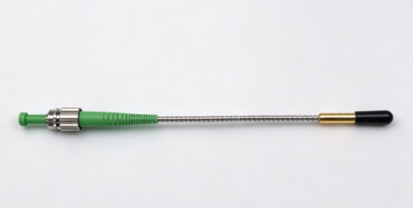
Why Choose an Armored Fiber Pigtail for a 2000 nm PM Fiber Collimator?
For optical systems operating in the 1950–2000 nm wavelength range, a polarization-maintaining (PM) fiber collimator needs to deliver reliable optical performance while meeting the mechanical requirements of the installation environment. In high-power laser systems, fiber sensing, and precision optical testing, fiber protection is also an important consideration.
What are the benefits of choosing an armored fiber pigtail for a 2000 nm PM fiber collimator? Is it suitable for your application? This article explains the key specifications, product advantages, applications, selection guidelines, and frequently asked questions.
1. Why Choose an Armored Fiber Pigtail for a 2000 nm PM Fiber Collimator?
A PM fiber collimator converts light traveling through an optical fiber into a collimated free-space beam, or couples a free-space beam back into an optical fiber. It is widely used in optical systems that require stable polarization and precise optical path control.
Compared with a standard fiber pigtail, an armored pigtail typically incorporates a protective metal tube or another reinforced structure around the fiber. This provides additional protection against external impacts, abrasion, compression, and accidental bending during installation and routing.
The main benefits of an armored fiber pigtail include:
- Enhanced mechanical protection: The armored layer provides additional protection for the internal fiber, reducing the risk of external mechanical damage.
- Improved cable routing reliability: It helps protect the fiber during equipment installation, laboratory setup, and cable management.
- Adaptability to complex installation environments: It is suitable for systems with limited space, sharp equipment edges, or fiber routing requirements that increase the risk of damage.
- Reduced maintenance risks: Better mechanical protection can help reduce fiber replacement and equipment downtime caused by accidental damage.
It is important to note that armoring primarily improves mechanical protection. It does not directly increase the collimator’s extinction ratio, reduce its insertion loss, or improve its return loss. Actual protection depends on the armor material, structural design, minimum bend radius, and strain-relief configuration.
2. Key Specifications of the 2000 nm PM Fiber Collimator
The working distance and fiber configuration can be customized according to application requirements.
2.1 Center Wavelength: 1950–2000 nm
This near-infrared wavelength range is suitable for certain 2 μm laser systems and related optical experiments.
2.2 Typical Insertion Loss: 0.3 dB
The typical insertion loss is 0.3 dB, indicating the typical optical power loss as light passes through the collimator.
Low insertion loss helps minimize optical power loss and is beneficial for laser transmission and optical testing systems where optical efficiency is important.
2.3 Working Distance: 80 mm (Customizable)
The standard working distance is 80 mm and can be customized according to the optical system design.
2.4 Extinction Ratio: >18 dB
The extinction ratio measures the relative suppression of two orthogonal polarization components and is an important indicator of polarization-maintaining performance.
2.5 Return Loss: >55 dB
Return loss measures the amount of reflected optical power returning toward the light source relative to the incident optical power. A higher return loss generally indicates lower back reflection.
3. Key Product Advantages
3.1 Designed for the 2 μm Wavelength Range
With an operating wavelength range of 1950–2000 nm, the collimator is suitable for applications requiring optical transmission, beam collimation, and polarization control in this spectral region.
Ensure that all optical components in the system are compatible with the target wavelength.
3.2 Low Typical Insertion Loss
The typical insertion loss of 0.3 dB helps control optical power loss and supports applications where efficient optical transmission is important.
3.3 Polarization-Maintaining Performance and Low Back Reflection
An extinction ratio greater than 18 dB and a return loss greater than 55 dB provide useful performance specifications for polarization-sensitive and low-reflection optical systems.
3.4 80 mm Working Distance with Customization Options
The standard working distance is 80 mm, with customization available according to the optical layout and mechanical requirements of the application.
This flexibility makes integration into different experimental setups and optical devices easier.
3.5 Additional Mechanical Protection with an Armored Pigtail
An armored fiber pigtail is suitable for equipment that requires additional fiber protection and reliable long-term operation.
By selecting the appropriate armor structure, fiber length, and strain-relief design, users can better accommodate their installation requirements.
4. Applications of 2000 nm PM Fiber Collimators
4.1 2 μm Laser Systems
Suitable for beam transmission, collimation, and experimental optical setups using certain laser systems operating within the 1950–2000 nm range.
Application suitability depends on laser power, beam characteristics, and overall system design.
4.2 Fiber Optic Sensing Systems
In fiber sensing systems that require polarization control, PM fiber collimators can be used for optical coupling and beam collimation.
An armored pigtail helps reduce the risk of mechanical damage during equipment installation and cable routing.
4.3 Optical Experiments and Test Equipment
In laboratory platforms, optical measurement instruments, and precision testing equipment, collimators help establish controlled beam output and optical coupling.
A customizable working distance allows greater flexibility when integrating the collimator into different mechanical layouts.
4.4 Industrial Laser Equipment
For certain near-infrared laser systems, an armored pigtail provides additional fiber protection.
However, applications involving high optical power, elevated temperatures, vibration, or frequent movement require separate evaluation of power handling, thermal management, and dynamic bending lifetime.
5. How to Select the Right 2000 nm PM Fiber Collimator
Before purchasing, consider the following factors.
Step 1: Confirm the operating wavelength.
Specify whether the operating wavelength is 1950 nm, 2000 nm, or another wavelength within the range. Confirm that the fiber and optical coatings are suitable for the target wavelength.
Step 2: Define the polarization requirements.
Evaluate whether an extinction ratio greater than 18 dB meets your system requirements. If stricter polarization performance is needed, communicate this requirement before ordering.
Step 3: Determine the working distance and beam requirements.
Provide the required working distance, beam diameter, divergence angle, and relevant receiving-side optical parameters to assess compatibility with your optical design.
Step 4: Choose the appropriate fiber protection structure.
If the pigtail may be exposed to compression, abrasion, or accidental bending, consider an armored configuration.
Confirm the armor’s outer diameter, flexibility, length, end fixing method, and minimum bend radius.
Step 5: Confirm optical power and environmental conditions.
For high-power laser applications, provide the operating mode (continuous-wave or pulsed), average power, peak power, and beam parameters.
Wavelength compatibility alone is not sufficient to determine whether a collimator is suitable for high-power operation.
6. Frequently Asked Questions (FAQ)
Q1: Does an armored fiber pigtail improve the extinction ratio of a PM fiber collimator?
No, not directly. The extinction ratio mainly depends on the PM fiber, optical coupling, stress control, and product design.
An armored pigtail primarily provides additional mechanical protection and does not replace proper polarization-performance design.
Q2: Can an armored fiber pigtail never bend or become damaged?
No. Armored fiber pigtails still have specified bending limits and mechanical load limitations.
Avoid excessive bending, twisting, pulling, and repeated flexing during installation. Always follow the supplier’s recommended routing and handling requirements.
Q3: Can the 80 mm working distance be customized?
Yes. Customization can be evaluated according to your requirements.
Provide the desired working distance and relevant beam parameters so the supplier can assess the appropriate design.
Q4: Is this collimator compatible with all 2 μm lasers?
Not necessarily. Compatibility depends on more than wavelength.
Laser power, continuous-wave or pulsed operation, fiber type, polarization requirements, and optical coating compatibility must also be evaluated.
Q5: How can I determine whether a typical insertion loss of 0.3 dB meets my requirements?
Evaluate the specification against the total optical loss budget of your system.
Confirm whether 0.3 dB is a typical value or a guaranteed maximum. If the project has strict loss acceptance criteria, specify the required test conditions and acceptance limits when requesting a quotation.
7. Purchasing Consultation: Get a Solution for Your Optical System
If you are looking for a PM fiber collimator operating at 1950–2000 nm with an armored fiber pigtail, we recommend providing the following information when requesting a quotation:
- Operating wavelength and laser power
- Required working distance and beam parameters
- Extinction ratio and insertion loss requirements
- Fiber length, armor configuration, and installation space
- Connector type or bare-fiber output requirements
- Estimated order quantity and special operating conditions
Conclusion
For PM fiber collimators operating within the 1950–2000 nm wavelength range, the main benefit of choosing an armored fiber pigtail is enhanced mechanical protection, improved routing flexibility, and a reduced risk of accidental fiber damage during installation and operation.
With a typical insertion loss of 0.3 dB, an extinction ratio greater than 18 dB, a return loss greater than 55 dB, and a customizable working distance of 80 mm, this product provides useful specifications for evaluating optical system requirements.
Comments are closed