Fiber Optic Connector Insertion Loss and Return Loss: Principles and Optimization Methods
In high-speed optical communication networks, data centers, CATV systems, fiber sensing, and fiber laser applications, fiber optic connectors play a critical role in transmitting optical signals. The performance of a connector directly affects the stability and reliability of the entire system. Among various specifications, Insertion Loss (IL) and Return Loss (RL) are two of the most important parameters used to evaluate connector performance.
Understanding the factors that influence these parameters and how to optimize them is essential for improving transmission quality and minimizing system failures.
What Is Insertion Loss (IL)?
Insertion Loss refers to the optical power loss that occurs when a connector is inserted into an optical path. It is expressed in decibels (dB).
Formula:
IL (dB) = 10 log (Pin / Pout)
Where:
- Pin = Input optical power
- Pout = Output optical power
A lower insertion loss indicates higher optical transmission efficiency.
Typical Insertion Loss Values
| Connector Type | Typical Insertion Loss |
|---|---|
| FC/PC | ≤0.3 dB |
| SC/PC | ≤0.3 dB |
| LC/UPC | ≤0.2 dB |
| FC/APC | ≤0.3 dB |
| MPO/MTP | ≤0.35 dB |
High-quality connectors can typically achieve:
0.1–0.2 dB insertion loss
What Is Return Loss (RL)?
Return Loss is a measure of the amount of light reflected back toward the optical source. It represents the ratio between the input optical power and the reflected optical power.
Formula:
RL (dB) = 10 log (Pin / Preflected)
A higher return loss value indicates lower back reflection and better connection quality.
Typical Return Loss Values
| Connector Type | Return Loss |
|---|---|
| PC | ≥40 dB |
| UPC | ≥50 dB |
| APC | ≥60 dB |
| Ultra-Low Reflection APC | ≥65 dB |
For high-power fiber lasers, DWDM systems, and coherent communication systems, a return loss above 60 dB is generally required.
Factors Affecting Insertion Loss
1. Fiber Core Size Mismatch
Connecting fibers with different core sizes can cause coupling losses, such as:
- 9/125 μm single-mode fiber
- 50/125 μm multimode fiber
- 62.5/125 μm multimode fiber
The greater the mismatch, the higher the insertion loss.
2. Core Misalignment
If the fiber cores are not perfectly aligned, part of the optical power cannot be coupled into the receiving fiber.
Even a core offset of 1 μm may introduce:
0.1–0.3 dB additional loss
3. End-Face Quality
Contaminants and defects on the connector end face, including:
- Dust
- Oil contamination
- Scratches
- Chips
can lead to optical scattering and increased attenuation.
According to industry statistics:
More than 80% of fiber link failures are caused by connector contamination.
4. Air Gap Between Fiber End Faces
Insufficient physical contact between ferrules creates an air gap, which increases:
- Fresnel reflections
- Insertion loss
5. Radius of Curvature and Apex Offset
Poor polishing geometry may result in:
- Insufficient contact pressure
- Imperfect fiber-to-fiber contact
which ultimately increases insertion loss.
Factors Affecting Return Loss
Fresnel Reflection
Differences in refractive indices between glass and air naturally generate reflections.
For a flat fiber end face, the reflection level is approximately:
-14 dB
Therefore, Physical Contact (PC) or Angled Physical Contact (APC) polishing is used to reduce reflections.
End-Face Contamination
Dust and oil contamination may create microscopic air gaps, resulting in:
- Reduced return loss
- Laser instability
- Mode hopping in laser systems
End-Face Angle Errors
APC connectors feature an 8° angled end face.
Excessive angle deviation can lead to:
- Lower return loss
- Reflected light re-entering the fiber core
How to Optimize Insertion Loss and Return Loss
1. Keep Connector End Faces Clean
Recommended cleaning tools include:
- Lint-free wipes
- Isopropyl alcohol (IPA)
- One-click fiber cleaners
- Fiber end-face inspection microscopes
Follow the industry best practice:
Inspect Before Connect
2. Use High-Precision Ceramic Ferrules
Premium zirconia ceramic ferrules provide:
- Concentricity ≤0.5 μm
- Excellent mechanical stability
- Superior repeatability
These characteristics help minimize insertion loss.
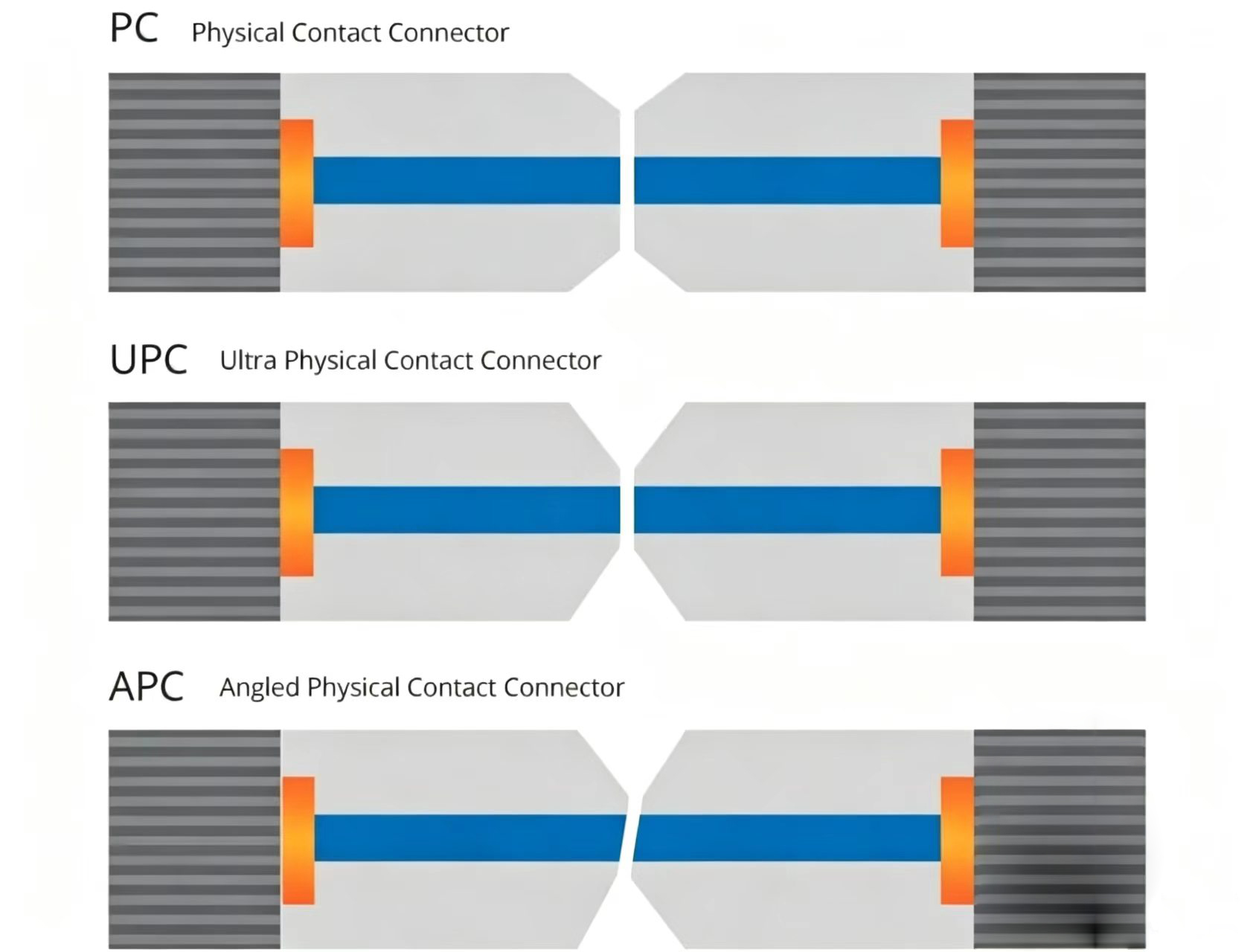
3. Select the Appropriate End-Face Type
PC Connectors
- RL ≥40 dB
- Cost-effective
Suitable for:
- Standard optical communication systems
UPC Connectors
- RL ≥50 dB
Suitable for:
- Data centers
- CATV networks
- FTTH applications
APC Connectors
- RL ≥60 dB
Suitable for:
- DWDM systems
- EDFA amplifiers
- Fiber sensing
- High-power fiber lasers
4. Improve Polishing Accuracy
Strict control of the following parameters is essential:
- Radius of curvature
- Apex offset
- Fiber height
- End-face angle
This enables performance levels of:
- Insertion Loss ≤0.15 dB
- Return Loss ≥60 dB
5. Use High-Quality Connector Components
Premium fiber optic connectors feature:
- Low-eccentricity fibers
- Precision ceramic sleeves
- Advanced polishing processes
- 100% factory testing
These characteristics provide:
- Lower insertion loss
- Higher return loss
- Longer service life
Performance Comparison of PC, UPC, and APC Connectors
| Parameter | PC | UPC | APC |
|---|---|---|---|
| Insertion Loss | ≤0.3 dB | ≤0.2 dB | ≤0.3 dB |
| Return Loss | ≥40 dB | ≥50 dB | ≥60 dB |
| End-Face Angle | 0° | 0° | 8° |
| Reflection Level | Higher | Low | Extremely Low |
| Typical Applications | Standard Telecom | Data Centers, FTTH | DWDM, Fiber Lasers |
Conclusion
As technologies such as 400G/800G data centers, 5G networks, fiber sensing, and high-power fiber lasers continue to evolve, increasingly stringent requirements are being placed on connector performance. Lower insertion loss and higher return loss are essential for maximizing transmission efficiency, reducing reflection-induced interference, and improving overall network reliability.
By utilizing precision ceramic ferrules, optimizing polishing geometry, maintaining strict manufacturing controls, and keeping connector end faces clean, it is possible to achieve:
Ultra-Low Insertion Loss (≤0.15 dB)
High Return Loss (≥60 dB)
These characteristics provide a solid foundation for high-speed optical communication networks and other mission-critical optical applications.
About Xionghua Photoelectric
Xionghua Photoelectric specializes in the development and manufacturing of high-performance fiber optic connectors, optical switches, polarization-maintaining components, and fiber optic assemblies. We offer a wide range of connector interfaces, including FC, SC, LC, ST, E2000, and MPO, with low insertion loss, high return loss, and customized solutions to meet the demanding requirements of telecommunications, data centers, fiber lasers, and fiber sensing applications.
Comments are closed