


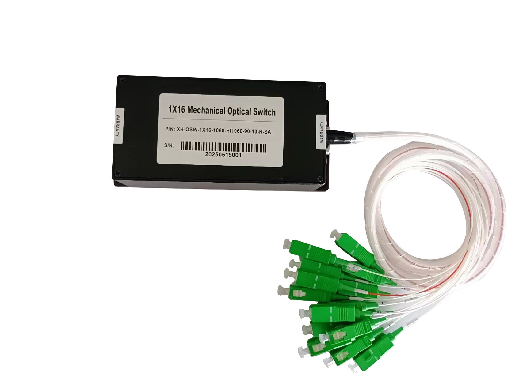
Mechanical Optical Switch Troubleshooting Guide: Common Faults, Self-Checks, and Solutions
Introduction
Mechanical optical switches are widely used in fiber optic communication systems, optical testing equipment, fiber sensing, and automated measurement systems. By mechanically switching the optical path between different input and output ports, they enable flexible optical signal routing without manually reconnecting fiber cables.
Although mechanical optical switches are designed for reliable operation, users may occasionally encounter issues such as signal loss, switching failures, communication errors, or unexpected status indicators.
In many cases, these problems can be identified through a few simple self-checks before contacting technical support. This guide explains how to troubleshoot common mechanical optical switch problems and provides practical solutions to help restore normal operation.
1. Optical Signal Loss or No Optical Output
Possible causes:
- Fiber connectors are loose, contaminated, or improperly connected.
- Input and output ports are incorrectly connected.
- The optical fiber or connector is damaged.
- The optical source is not operating normally.
- The optical switch has excessive insertion loss or an internal optical path issue.
Troubleshooting steps:
- Check whether the optical source is operating and providing sufficient optical power.
- Verify that the input and output fibers are connected to the correct ports.
- Inspect the fiber connectors and clean them using appropriate fiber optic cleaning tools.
- Use an optical power meter to measure the input and output power.
- Compare the measured insertion loss with the product specifications.
If the input optical power is normal but the output power is significantly lower than expected, test the fiber connections and, if possible, compare the results across different switch channels.
Tip: Always inspect and clean optical connectors before performing detailed measurements. Connector contamination is a common cause of unexpected insertion loss in fiber optic systems.
2. Mechanical Optical Switch Fails to Change Channels
Possible causes:
- The control command is incorrect.
- The power supply is unstable or disconnected.
- The communication interface is improperly configured.
- The control software is incompatible with the device.
- The switch has encountered a mechanical or internal hardware fault.
Troubleshooting steps:
- Confirm that the optical switch is receiving the correct supply voltage.
- Check the selected channel and verify that the switching command matches the device’s control protocol.
- If the switch is controlled through RS232, USB, or Ethernet, verify the connection and interface settings supported by the specific model.
- Restart the control software and, if appropriate, power-cycle the device according to the manufacturer’s instructions.
- Test another channel to determine whether the problem affects one channel or the entire device.
If the switch still cannot change channels, record the command sent, the selected channel, and any indicator or error messages. These details can help technical support identify the cause more efficiently.
3. Communication Failure Between the Switch and Computer
For computer-controlled optical switches, communication problems may prevent the device from receiving commands or reporting its status correctly.
Possible causes:
- An incorrect COM port is selected.
- The serial communication parameters do not match.
- The USB-to-serial driver is missing or incompatible.
- The communication cable is defective.
- The control software does not support the device’s interface or protocol.
Troubleshooting steps:
- Check whether the computer recognizes the device or its USB-to-serial adapter.
- Verify the COM port and communication parameters specified in the product manual.
- Confirm that the control software is compatible with the switch model.
- Inspect the cable connections and try another compatible cable if available.
- For Ethernet-controlled models, verify the network connection and the configured IP address.
Note that different optical switch models may use different control interfaces and protocols. For example, a USB connection may serve as a serial interface rather than a direct Ethernet connection. Always follow the interface specifications of the actual device.
4. Inconsistent Insertion Loss Between Switching Channels
Insertion loss may vary between channels because of differences in optical alignment, connector condition, fiber routing, or measurement setup.
Possible causes:
- Dirty or worn fiber connectors.
- Excessive fiber bending.
- Different connector or adapter conditions.
- Incorrect optical power meter settings.
- An issue affecting a particular internal optical path.
Troubleshooting steps:
- Use the same optical source, wavelength, and measurement setup when comparing channels.
- Clean and reconnect the fiber connectors.
- Check the fiber routing for tight bends, pulling, or other mechanical stress.
- Measure each channel under consistent conditions.
- Compare the results against the specified insertion loss and channel-to-channel performance requirements.
If one channel consistently shows abnormal loss after external connections and measurement conditions have been verified, contact the manufacturer for further evaluation.
5. Unexpected Status Indicators or Abnormal Operation
Some mechanical optical switches include status LEDs, LCD displays, or software-based status indicators.
If the displayed status does not match the selected channel, first verify whether the device has completed the switching operation. Check the control software, communication connection, and power supply.
If the device supports local manual control, use the approved procedure to determine whether the problem is limited to remote control or also occurs during local operation.
Do not open the enclosure or attempt internal mechanical adjustments unless authorized by the manufacturer. Unauthorized disassembly may affect alignment, performance, or warranty coverage.
6. A Practical Self-Check Checklist
Before contacting technical support, complete the following checks:
-
Confirm that the power supply and power connections are normal.
-
Verify that the optical input and output fibers are connected correctly.
-
Inspect and clean the fiber connectors.
-
Confirm that the optical source is functioning properly.
-
Check the control interface, communication settings, and software compatibility.
-
Test the switching operation across the relevant channels.
-
Measure optical power and insertion loss using a consistent setup.
-
Record the device model, operating wavelength, affected channel, and observed symptoms.
These checks can help distinguish external connection problems, control configuration errors, and possible device-related faults.
7. When Should You Contact the Manufacturer?
If the mechanical optical switch continues to exhibit abnormal behavior after the basic checks, further technical evaluation may be necessary.
When requesting support, provide the following information:
- Optical switch model and port configuration.
- Operating wavelength and optical power.
- Description of the problem and the conditions under which it occurs.
- Control interface and software settings, if applicable.
- Optical power or insertion loss measurements.
- Photos, screenshots, or a short video showing the issue.
Providing these details helps the manufacturer evaluate the problem more efficiently and recommend appropriate corrective actions.
Conclusion
Routine self-checks can help users identify many common mechanical optical switch problems, including optical signal loss, channel switching failures, communication errors, and abnormal insertion loss.
Checking the power supply, fiber connections, connector cleanliness, control settings, and optical performance should be the first step in most troubleshooting procedures. If the problem persists, consult the manufacturer rather than attempting unauthorized internal repairs.
Comments are closed