


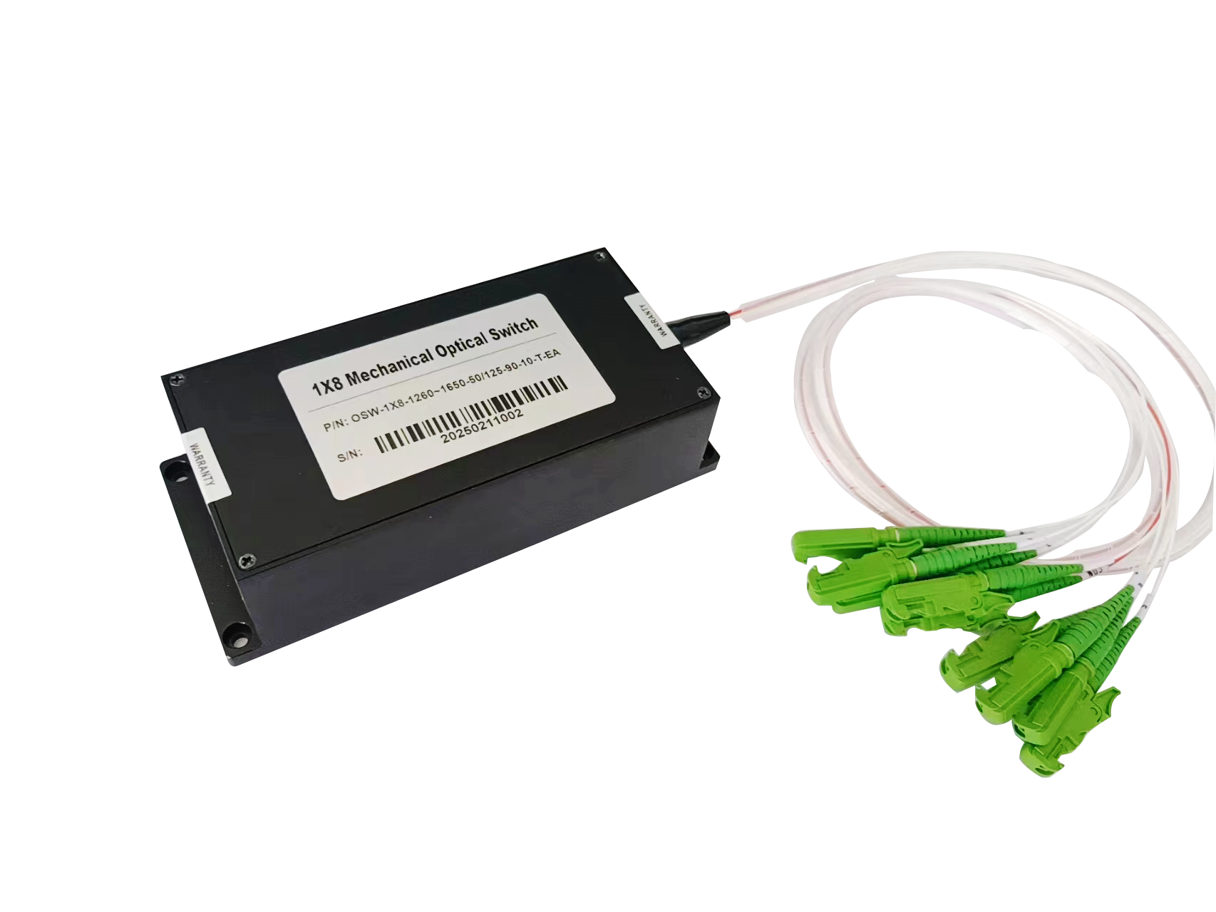
Optical Switch Crosstalk: Causes, Effects, and How to Minimize It
Introduction
Optical switches play an important role in fiber optic communication, optical testing, fiber sensing, and automated test systems. By directing optical signals between different fiber paths, they enable flexible optical routing without manually reconnecting fibers.
However, one important performance factor that engineers should consider when selecting an optical switch is crosstalk.
Excessive optical crosstalk can introduce unwanted optical signals into the selected output path, potentially affecting measurement accuracy, signal quality, and system reliability. Understanding what causes crosstalk and how to minimize it can help engineers choose the right optical switch for their applications.
1. What Is Optical Switch Crosstalk?
Optical switch crosstalk refers to unwanted optical power that leaks from an unselected optical path into the selected output path.
Ideally, an optical switch should transmit the intended optical signal while effectively isolating all other input or output paths. In practice, however, a small amount of optical energy may reach an unintended path due to limitations in optical isolation, internal reflections, or other optical effects.
Crosstalk is commonly expressed in decibels (dB). It is often specified as a negative value relative to the desired signal, although some datasheets express it as a positive isolation value. Therefore, it is important to check the manufacturer’s measurement definition when comparing products.
In general, a more negative crosstalk value indicates less unwanted optical leakage and better isolation between optical paths.
2. What Causes Crosstalk in Optical Switches?
Several factors can contribute to optical switch crosstalk.
2.1 Limited Optical Isolation
Optical switches must isolate the selected channel from unselected channels. If the isolation between optical paths is insufficient, a portion of the optical signal may leak into another path.
This is particularly important in systems that use multiple channels or require accurate measurements of weak optical signals.
2.2 Internal Optical Reflections
Reflections from optical interfaces, connectors, or internal optical components can create unwanted optical paths. Depending on the switch design and system configuration, these reflections may contribute to interference or additional optical leakage.
Proper optical alignment, suitable connector selection, and good end-face cleanliness can help reduce reflection-related problems.
2.3 Optical Component Design and Alignment
Different optical switch technologies use different mechanisms to route light. MEMS optical switches, mechanical optical switches, and other switching technologies may exhibit different crosstalk characteristics depending on their optical design, manufacturing quality, and alignment accuracy.
For this reason, crosstalk should be evaluated alongside insertion loss, repeatability, switching performance, and reliability rather than used as the only selection criterion.
2.4 Connector Contamination and Improper Connections
Dust, oil, scratches, and poorly connected fiber interfaces can affect optical transmission and reflection. Although connector contamination does not always directly increase the switch’s intrinsic crosstalk, it can introduce unwanted optical effects and make system-level measurements less reliable.
Cleaning and inspecting fiber connectors before testing is an essential step.
3. How Does Crosstalk Affect Optical Communication and Testing?
The impact of crosstalk depends on the application and the strength of the unwanted signal relative to the desired signal.
Optical communication systems: Unwanted optical signals may interfere with channel measurements and, in some configurations, degrade signal quality.
Optical testing systems: Crosstalk can affect the accuracy of measurements when the system needs to distinguish a weak signal from signals on other channels.
Fiber optic sensing: Small unwanted signals may complicate the detection of weak optical responses, particularly in sensitive measurement systems.
Automated test equipment: Crosstalk between switch channels may lead to misleading test results or make it more difficult to verify the performance of individual optical paths.
In applications where weak signals must be measured accurately, low crosstalk and high channel isolation are especially important.
4. How Is Optical Switch Crosstalk Measured?
Crosstalk is typically evaluated by comparing the optical power transmitted through the intended path with the unwanted power detected at an unselected path.
A general measurement procedure includes the following steps:
- Connect a stable optical source to the input of the optical switch.
- Connect suitable optical power measurement equipment to the selected and unselected output paths, using a measurement arrangement appropriate for the switch configuration.
- Select the intended optical path and record the desired signal power.
- Measure the unwanted optical power at the relevant unselected path.
- Calculate the crosstalk according to the manufacturer’s specified definition and measurement method.
For example, when crosstalk is defined as the unwanted optical power relative to the desired optical power, it can be calculated as:
Crosstalk (dB) = 10 log₁₀ (Unwanted Optical Power / Desired Optical Power)
The result is normally negative when the unwanted optical power is lower than the desired optical power.
Actual test results depend on the optical source, wavelength, switch configuration, measurement equipment, and test conditions. Engineers should therefore use consistent test methods when comparing different optical switches.
5. How to Minimize Optical Switch Crosstalk
To improve optical isolation and measurement reliability, consider the following practices.
Choose a Switch with Suitable Crosstalk Performance
Check the manufacturer’s crosstalk or channel-isolation specifications and confirm that they meet the requirements of your application. Do not assume that all optical switches with the same port configuration have equivalent performance.
Evaluate the Complete Optical Path
System performance depends on more than the switch itself. Connectors, fiber components, couplers, and other optical devices can affect the overall measurement. Evaluate the complete optical path when diagnosing unexpected leakage.
Maintain Clean Fiber Connections
Inspect and clean optical connectors before testing. Damaged or contaminated end faces may cause additional loss and reflections, affecting the consistency of measurement results.
Use Consistent Measurement Conditions
Keep the wavelength, input power, connection method, and measurement configuration consistent when comparing devices. Confirm the manufacturer’s definition of crosstalk to avoid comparing results obtained using different methods.
Select the Appropriate Switch Technology
MEMS and mechanical optical switches can both be suitable for different applications. Selection should be based on the required optical performance, switching behavior, port count, control interface, reliability, and operating environment.
6. How to Select an Optical Switch with Low Crosstalk
Before purchasing an optical switch, engineers should evaluate several key factors:
- Crosstalk and optical isolation: Confirm the required level of separation between channels.
- Insertion loss: Ensure that the desired optical signal can pass through the switch with acceptable loss.
- Wavelength range: Select a switch compatible with the operating wavelength of the system.
- Fiber type: Verify compatibility with single-mode, multimode, or polarization-maintaining fiber as required.
- Port configuration: Choose a suitable switching configuration, such as 1×2, 1×4, 1×8, or 1×16.
- Control interface: Confirm compatibility with the system’s control requirements, such as RS232, TTL, or other available interfaces.
- Application requirements: Consider whether the switch will be used for optical communication, laboratory testing, fiber sensing, or automated measurement.
For demanding applications, it is advisable to confirm the crosstalk specification and measurement conditions with the manufacturer before placing an order.
Conclusion
Optical switch crosstalk is an important factor affecting channel isolation and the reliability of optical measurements. It can result from limited optical isolation, internal reflections, component alignment, and other factors within the optical path.
By understanding the causes of crosstalk, using consistent measurement methods, maintaining clean fiber connections, and selecting a switch with appropriate optical performance, engineers can improve system reliability and measurement accuracy.
Comments are closed