


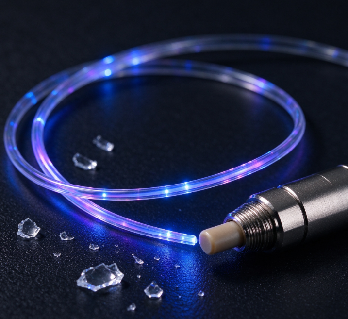
Optical Fiber Bend Radius and Macrobending Loss: 1550 nm vs 1310 nm, G.657 vs G.652
Introduction
Optical fiber bending is a common but often overlooked source of signal attenuation in fiber optic communication and testing systems. When an optical fiber is bent too tightly, some of the guided light can escape from the core, resulting in additional optical power loss. This phenomenon is known as macrobending loss.
The amount of loss depends on several factors, including bend radius, operating wavelength, fiber design, and installation conditions. In particular, 1550 nm and 1310 nm can exhibit different bending sensitivities, while G.657 and G.652 single-mode fibers offer different levels of bending performance.
Understanding these differences helps engineers select suitable optical fibers, improve installation reliability, and minimize unnecessary signal loss.
1. What Is Optical Fiber Macrobending Loss?
Macrobending loss occurs when an optical fiber is bent into a visible curve with a radius that is too small for the fiber’s optical characteristics.
Under normal conditions, light travels through the fiber core because of the fiber’s refractive-index structure. When the fiber bends, the optical field on the outer side of the curve becomes less effectively confined. Some optical energy can escape from the guided mode, increasing attenuation.
Unlike connector loss or splice loss, macrobending loss is directly associated with the fiber’s bending conditions.
Several factors influence this loss:
- Bend radius: Tighter bends generally produce higher loss.
- Operating wavelength: Longer wavelengths are generally more sensitive to macrobending in comparable fiber designs.
- Fiber design: The refractive-index profile and mode confinement affect bending resistance.
- Number of bends: Multiple bends can contribute to cumulative attenuation.
- Installation conditions: Improper routing, tight cable ties, and crowded enclosures can increase bending-related loss.
Macrobending loss is especially important in fiber optic networks, compact optical modules, high-density patch panels, and precision optical testing systems.
2. Why Is Macrobending Loss Different at 1550 nm and 1310 nm?
The operating wavelength plays an important role in fiber bending performance.
For the same fiber under comparable bending conditions, macrobending loss is generally more pronounced at 1550 nm than at 1310 nm. This is because the optical field at the longer wavelength is typically less tightly confined, making it more susceptible to radiation loss when the fiber bends.
Macrobending Loss at 1310 nm
The 1310 nm wavelength is widely used in single-mode fiber communication systems. Under comparable bending conditions, it generally exhibits lower macrobending sensitivity than 1550 nm.
However, this does not mean that bending loss at 1310 nm can always be ignored. A very small bend radius, repeated bending, or unsuitable fiber routing can still cause measurable attenuation.
Macrobending Loss at 1550 nm
The 1550 nm wavelength is widely used in optical transmission systems because of its favorable transmission characteristics in conventional silica fiber.
However, it is generally more sensitive to macrobending. A fiber installation that performs acceptably at 1310 nm may show increased attenuation at 1550 nm when tight bends are present.
This difference is important when troubleshooting optical links or evaluating fiber performance across multiple wavelengths.
Practical tip: If a system shows unexpected attenuation at 1550 nm but performs better at 1310 nm, inspect the fiber routing and bend radius before assuming that the problem comes from a connector, splice, or optical component.
The actual loss difference depends on fiber design, bend radius, and the number of turns. It should be measured rather than estimated using a universal conversion factor.
3. G.657 vs G.652: Understanding the Difference
G.652 and G.657 are two important ITU-T recommendations for single-mode optical fibers. Both are used in optical communication, but their bending characteristics differ.
G.652: Conventional Single-Mode Optical Fiber
G.652 fiber is widely deployed in telecommunications infrastructure, metropolitan networks, and general-purpose optical transmission systems.
It offers established transmission characteristics and is suitable for many installations where sufficient space is available to maintain the recommended bend radius.
However, conventional G.652 fiber can experience higher macrobending loss when routed through tight corners or compact enclosures, particularly at 1550 nm.
For installations with limited space, careful cable management is essential to avoid unnecessary attenuation.
G.657: Bend-Insensitive Optical Fiber
G.657 fiber is designed to improve resistance to macrobending loss. It is particularly useful where optical fibers must be routed through compact spaces or around tighter curves.
Common applications include fiber-to-the-home installations, indoor optical networks, distribution boxes, patch panels, and compact fiber optic equipment.
Different G.657 categories provide different bending performance:
- G.657.A1: Improved bending performance while maintaining compatibility with G.652 fiber characteristics.
- G.657.A2: Supports tighter bending requirements and is suitable for many access-network installations.
- G.657.B3: Designed for very small bend radii in specialized, space-constrained applications.
The categories have different requirements and should not be treated as identical. Always consult the applicable ITU-T recommendation and the manufacturer’s specifications when selecting a fiber.
The primary advantage of G.657 is its ability to reduce bending-related loss in situations where conventional G.652 fiber may experience greater attenuation.
4. How Does Bend Radius Affect Optical Fiber Performance?
Bend radius is one of the most important factors affecting macrobending loss.
A larger bend radius generally allows light to remain confined within the fiber more effectively. As the radius decreases, the risk of optical power escaping from the guided mode increases.
The relationship between bend radius and loss is nonlinear. A relatively small reduction in bend radius can sometimes cause a significant increase in attenuation.
For example, a fiber routed smoothly around a broad curve may introduce negligible additional loss. The same fiber routed sharply around the edge of an enclosure may produce measurable attenuation.
G.657 fiber can tolerate tighter bends than conventional G.652 fiber under specified test conditions. Nevertheless, actual performance depends on the fiber category, operating wavelength, number of turns, and cable construction.
It is also important to distinguish optical bending performance from mechanical durability. A fiber that maintains low optical loss under a tight bend is not necessarily immune to mechanical damage.
For reliable long-term operation:
- Follow the manufacturer’s minimum bend-radius recommendations.
- Avoid sharp corners and excessive tension during installation.
- Do not overtighten cable ties around optical fibers.
- Keep fiber routing organized inside enclosures and patch panels.
- Consider both optical attenuation and mechanical reliability when choosing a fiber.
5. G.657 or G.652: Which Fiber Should You Choose?
The best choice depends on the installation environment and performance requirements.
Choose G.652 when:
- The application involves conventional optical transmission networks.
- There is sufficient space for proper fiber routing.
- The installation can maintain the recommended bend radius.
- Standard single-mode fiber characteristics meet the system requirements.
Consider G.657 when:
- Fibers must be routed through compact enclosures.
- Installation space is limited.
- Tight bends cannot be completely avoided.
- Low bending-related attenuation is important for indoor access networks or high-density fiber management.
For applications operating at 1550 nm, bend-insensitive fiber may be particularly beneficial when the installation involves constrained routing. However, fiber selection should consider the full system requirements rather than wavelength alone.
6. How to Troubleshoot Macrobending Loss
When an optical link exhibits unexpected attenuation, several practical checks can help identify whether bending is the cause.
Step 1: Inspect the Fiber Route
Check for tight loops, sharp corners, pinched cables, and excessive bending near connectors or cable entry points.
Step 2: Compare Measurements at Different Wavelengths
If the system supports measurements at both 1310 nm and 1550 nm, compare the results under consistent test conditions. Higher loss at 1550 nm may indicate bending sensitivity, although it does not by itself confirm the cause.
Step 3: Check the Fiber Type
Determine whether the installed fiber is G.652 or a bend-insensitive G.657 category. Confirm that its bending characteristics are appropriate for the installation.
Step 4: Review Connectors and Splices
Connector contamination, poor mating, and splice defects can also cause attenuation. Inspect and clean connectors using appropriate procedures before retesting.
Step 5: Repeat the Measurement
After correcting suspected tight bends, measure the optical loss again under the same conditions. A reduction in attenuation supports the conclusion that fiber routing contributed to the original loss.
For more reliable troubleshooting, document the operating wavelength, fiber type, bend radius, number of turns, and measurement method.
7. Applications Where Macrobending Performance Matters
Understanding fiber bending characteristics is valuable across several industries.
Telecommunications: Bend-insensitive fiber can help reduce attenuation in FTTH installations, indoor access networks, and compact distribution enclosures.
Data centers: High-density patch panels and equipment racks require organized fiber routing to maintain stable optical performance.
Fiber optic testing: Comparing attenuation at 1310 nm and 1550 nm can help identify wavelength-dependent bending effects.
Fiber sensing: Reliable optical transmission is important when fibers are routed around equipment or installed in confined spaces.
Optical modules and components: Compact internal fiber routing requires careful consideration of fiber type, bend radius, and optical loss.
Choosing an appropriate fiber and maintaining proper routing practices can help improve optical link reliability and reduce avoidable attenuation.
Conclusion
Optical fiber macrobending loss is influenced by operating wavelength, bend radius, fiber design, and installation conditions.
At comparable bending conditions, 1550 nm generally exhibits greater macrobending loss than 1310 nm. G.657 fibers offer improved bending performance compared with conventional G.652 fibers, making them particularly useful in space-constrained installations.
When selecting an optical fiber, consider the operating wavelength, required bend radius, installation environment, and acceptable attenuation. Proper fiber selection and routing can help maintain reliable optical transmission.
Comments are closed