


PM Fiber Splicing Extinction Ratio Drops from 40 dB to 25 dB: The Real Cause of Polarization Degradation Is Not Always the Fusion Splicer
In polarization-maintaining (PM) fiber systems, the extinction ratio (ER) is one of the most important parameters for evaluating polarization-maintaining performance.
Engineers may sometimes encounter a frustrating situation:
Before splicing, the PM fiber has an extinction ratio of 40 dB. After fusion splicing, however, the system’s extinction ratio drops to only 25 dB.
When this happens, the first reaction is often:
“Is there something wrong with the fusion splicer?”
However, the answer is not always that simple.
In many PM fiber splicing and testing applications, the real cause of an extinction ratio dropping from 40 dB to 25 dB is not necessarily the fusion splicer itself. Instead, the degradation may result from a combination of factors, including polarization axis misalignment, internal stress, thermal effects in the splice region, fiber handling, packaging stress, and even the test setup itself.
1. Why Does the Extinction Ratio Drop from 40 dB to 25 dB?
First, it is important to understand one key point:
The extinction ratio of a PM fiber assembly is not determined by splice quality alone.
Even if the splice has:
- Low insertion loss
- Good mechanical strength
- Excellent visual appearance
the polarization performance may still degrade.
The purpose of PM fiber is to maintain the polarization state of light along a specific polarization axis.
Once the fast axes or slow axes of two PM fibers are not perfectly aligned, part of the optical power can couple from one polarization axis to the other.
This creates polarization crosstalk.
The result is:
A lower extinction ratio.
Therefore:
Low insertion loss does not necessarily mean high extinction ratio.
This is one of the most commonly overlooked issues in PM fiber splicing.
2. The Most Common Cause: Polarization Axis Misalignment
One of the most common reasons for a reduction in extinction ratio is inaccurate polarization axis alignment.
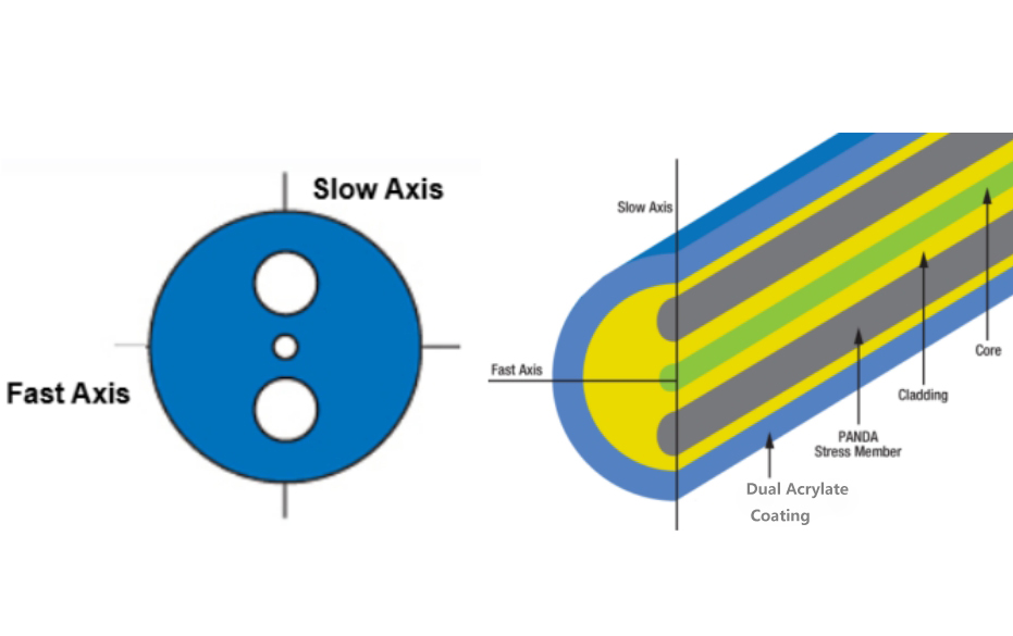
PM fibers typically contain structures designed to create birefringence, such as:
- Panda PM fiber
- Bow-Tie PM fiber
- Elliptical-core PM fiber
These structures define the fast and slow axes of the fiber.
During splicing, the polarization axes of the two PM fibers must be accurately aligned.
Even a small rotational angle error can increase polarization crosstalk.
For example:
- 0.5°
- 1°
- 2°
or even larger angular errors may affect the final extinction ratio.
Although the fibers may appear to be well aligned under the splicer’s microscope, high-extinction-ratio applications can be sensitive to very small alignment errors.
Therefore, when the extinction ratio drops from 40 dB to 25 dB, one of the first questions should be:
Are the polarization axes of the two PM fibers truly aligned with sufficient accuracy?
3. The Fusion Splicer May Align the Fiber Core, but Not the Polarization Axis
This is another critical issue.
For standard single-mode fiber splicing, the primary objective is usually:
To accurately align the fiber cores.
However, PM fiber requires more than core alignment.
It also requires:
Polarization axis alignment.
These are not exactly the same thing.
For example, two PM fiber cores may be perfectly aligned, while their slow axes still have a small rotational mismatch.
In this situation:
- The insertion loss may be very low.
- The splice may look excellent.
- The mechanical strength may be acceptable.
However:
The extinction ratio may still decrease significantly.
For high-performance PM fiber assemblies, appropriate PM fiber alignment technologies may be required, such as:
- PAS (Profile Alignment System)
- Stress rod alignment
- Profile alignment
- High-precision rotational alignment
To achieve better polarization performance, both of the following need to be controlled:
Fiber core alignment + polarization axis alignment
4. The Fiber Itself May Be Part of the Problem
Many engineers use the original extinction ratio of the PM fiber as the reference value.
For example:
“The PM fiber measured 40 dB before splicing, but only 25 dB afterward.”
However, it is important to remember:
The original extinction ratio of the fiber does not guarantee that the same value will be maintained throughout the entire manufacturing process.
During production, a PM fiber may go through:
- Coating stripping
- Cleaning
- Cleaving
- Rotational alignment
- Fusion splicing
- Heating
- Curing
- Coiling
- Packaging
Each process may potentially affect polarization performance.
In high-extinction-ratio applications, even mechanical stress and small bends can influence the polarization state.
Therefore, simply comparing:
40 dB before splicing → 25 dB after splicing
does not necessarily prove that the fusion splicer caused the degradation.
A better approach is to test the extinction ratio at different stages of the manufacturing process.
For example:
| Test Stage | Extinction Ratio |
|---|---|
| Original PM fiber | 40 dB |
| After stripping and cleaving | 38 dB |
| After fusion splicing | 30 dB |
| After fiber coiling | 27 dB |
| After packaging | 25 dB |
This type of step-by-step testing makes it much easier to identify where the extinction ratio begins to degrade.
5. Thermal Stress Can Be a Hidden Cause
Fusion splicing uses an electric arc to heat and soften the fiber ends.
During this process, the glass structure near the splice region experiences high temperatures.
If the splicing parameters are not optimized, such as:
- Arc power is too high
- Arc duration is too long
- Pre-fusion parameters are inappropriate
- The splice region is overheated
the stress distribution inside the fiber may change.
For standard single-mode fiber, this effect may not always be obvious.
However, PM fiber is more sensitive.
PM fiber relies on internal structures and stress-induced birefringence to maintain polarization.
For example, Panda PM fiber contains stress rods that create a specific stress distribution inside the fiber.
If excessive heat affects the splice region, the local birefringence characteristics may change.
As a result:
Additional polarization coupling may occur near the splice point.
For this reason, PM fiber should not always be spliced using the same parameters as standard single-mode fiber.
The fusion parameters should be optimized according to the specific PM fiber type.
6. Cleave Quality Can Also Affect the Extinction Ratio
Many people focus only on whether the fiber end face looks flat.
However, end-face quality is also important in high-performance PM fiber systems.
Poor cleaving may result in:
- End-face angle errors
- Small chips
- Edge damage
- Poor cleave quality
These problems can affect fiber positioning during the splicing process.
This may eventually lead to:
- Core misalignment
- Polarization axis misalignment
- An asymmetric splice region
Therefore, high-quality fiber end preparation is essential before PM fiber splicing.
This is especially important for PM fibers with small cores, high birefringence, or special structures.
7. Fiber Coiling: An Often Overlooked Cause of Polarization Degradation
After splicing, if the extinction ratio decreases significantly, another important factor to check is:
Is the fiber being bent too tightly?
PM fiber has polarization-maintaining properties, but this does not mean that it is completely immune to mechanical stress.
For example:
- Excessively small bend radius
- Fiber compression
- Fiber twisting
- Uneven coiling
- Pressure from fiber fixtures
may change the local stress distribution of the fiber.
This can create additional polarization coupling.
In some cases:
The extinction ratio is acceptable immediately after splicing.
But:
The extinction ratio drops significantly after the fiber is installed inside a module.
In this situation, the problem may not be the splice itself.
It may be:
Packaging stress.
8. Adhesives and Curing Processes Can Also Reduce ER
In PM fiber component manufacturing, fusion splicing is usually only one step in the production process.
Additional processes may include:
- UV adhesive fixing
- Epoxy fixing
- Thermal curing
- Metal tube packaging
- Fiber fixation
If an adhesive shrinks during curing, mechanical stress may be applied to the PM fiber.
This is particularly important when the adhesive is applied close to a bare fiber section.
Mechanical stress after curing can change the local birefringence of the fiber.
As a result, the polarization state may be affected.
Therefore, when the extinction ratio drops from 40 dB to 25 dB, an important question is:
Did the ER decrease immediately after fusion splicing, or only after packaging?
The answer can help identify the real source of the problem.
9. Incorrect Test Methods Can Also Turn 40 dB into 25 dB
In addition to the manufacturing process, the test method itself can affect the measured extinction ratio.
For example:
1. Unstable Polarization State of the Light Source
If the polarization state of the input light is unstable, the measured ER may fluctuate.
2. Incorrect Alignment of the Input Polarization Axis
If the input light is not accurately aligned with the fast or slow axis of the PM fiber, the final measurement may be affected.
3. Limited Accuracy of the Test System
Measuring an extinction ratio of 40 dB requires a high-quality test setup.
The test system may require:
- A highly polarized light source
- A stable polarizer
- A high-precision optical power meter
- Proper measurement procedures
If the test system itself introduces polarization crosstalk, the measured extinction ratio may be limited.
4. Fiber Movement During Testing
If the PM fiber is:
- Pulled
- Bent
- Twisted
during testing, the measured result may change.
Therefore, high-extinction-ratio testing requires a stable test environment.
10. How Can You Find the Real Cause of a 40 dB → 25 dB Drop?
The best approach is:
Step-by-step testing.
Do not simply compare:
Before splicing → After splicing
Instead, establish a complete testing process.
Step 1: Test the Original PM Fiber
Record:
- Input ER
- Output ER
- Fiber length
- Test wavelength
This confirms the original performance of the PM fiber.
Step 2: Test the Fiber After Preparation
After:
- Stripping
- Cleaning
- Cleaving
test the extinction ratio again.
If the ER has already decreased, the problem may be related to fiber handling or preparation.
Step 3: Test Immediately After Fusion Splicing
Before packaging the fiber, test the ER immediately after splicing.
If the extinction ratio decreases significantly at this stage, check:
- Polarization axis alignment
- Splicing parameters
- Fiber type compatibility
- PM fiber alignment mode
Step 4: Test After Fiber Coiling
Measure the extinction ratio after coiling the fiber.
Test different bend radii if necessary.
This can help determine whether mechanical stress is affecting the polarization state.
Step 5: Test After Packaging
If the ER decreases after packaging, investigate:
- Fiber fixing methods
- Adhesives
- Curing stress
- Fiber clamps
- Pressure from metal components
This step-by-step method can help identify the real source of the problem.
11. So, Is the Fusion Splicer Really the Problem?
The answer is:
It can be—but it should not be blamed immediately.
The fusion splicer can affect extinction ratio if:
- Polarization axis alignment accuracy is insufficient
- PM fiber recognition is inaccurate
- Rotational alignment is not precise enough
- Splicing parameters are not optimized
- Arc power control is unstable
However, when the ER drops from 40 dB to 25 dB, the entire process should be investigated.
The following factors should be carefully checked:
✓ Polarization axis alignment
✓ PM fiber type
✓ Fusion parameters
✓ Fiber end-face quality
✓ Thermal stress in the splice region
✓ Fiber coiling
✓ Packaging stress
✓ Adhesive curing
✓ Test methods
12. Conclusion: Extinction Ratio Degradation Is Often a System-Level Problem
PM fiber splicing is not simply:
Connecting two fibers together.
A successful PM fiber splice requires control of:
Optical performance + core alignment + polarization axis alignment + thermal stress + mechanical stress
Therefore, when you observe:
ER: 40 dB → 25 dB
do not immediately blame the fusion splicer.
A more important question is:
At which stage did the polarization state begin to change?
By performing step-by-step measurements throughout the manufacturing process, the actual cause of extinction ratio degradation can be identified more accurately.
In many cases, the real cause of polarization degradation is not the fusion splicer itself, but rather:
Incomplete polarization axis alignment, thermal stress, fiber handling, coiling stress, packaging pressure, adhesive curing, or limitations in the test system.
For high-performance PM fiber components, fusion splicing is only one part of the process.
The final extinction ratio is determined by the entire manufacturing, handling, testing, and packaging process.
Comments are closed