


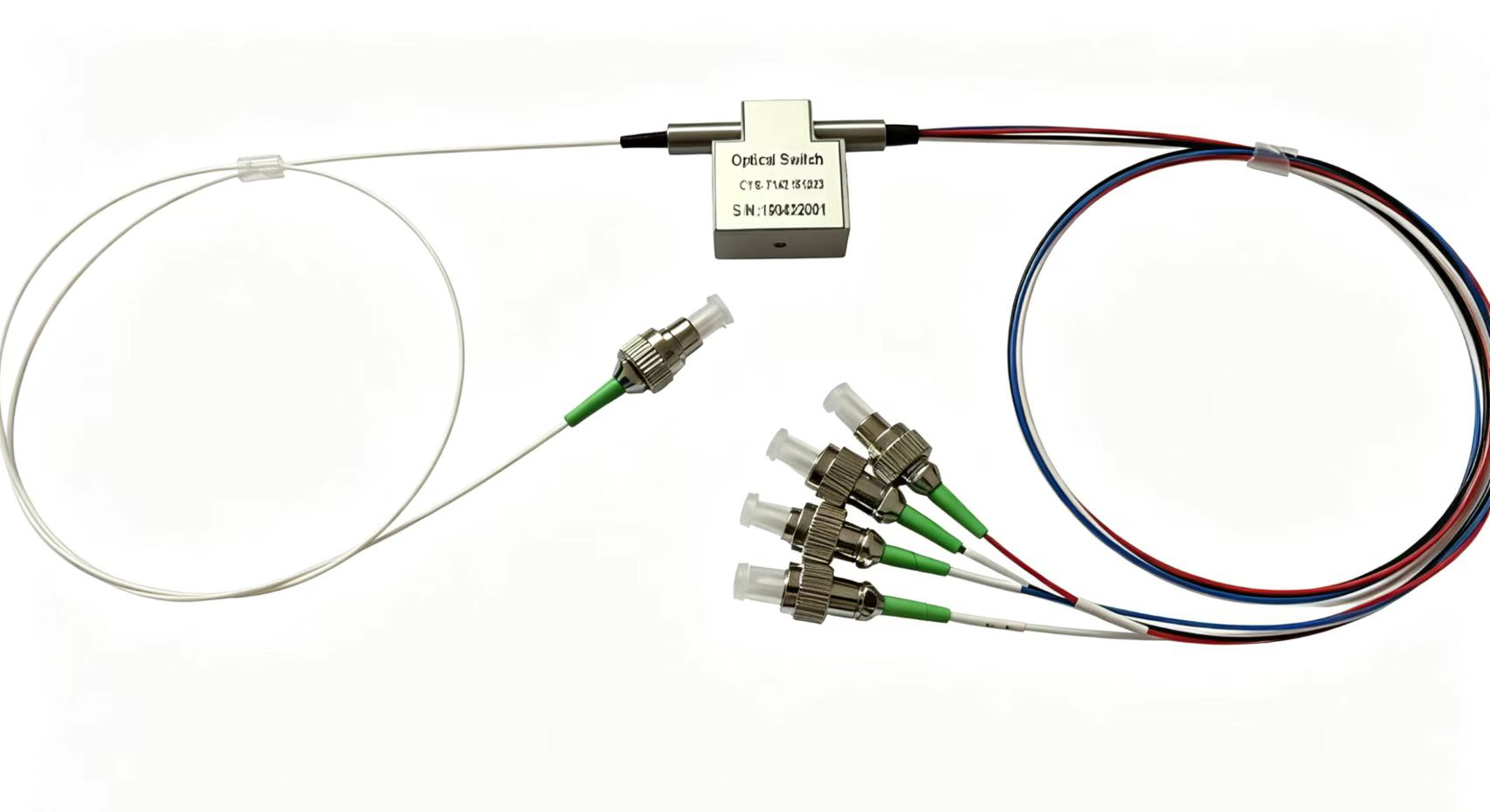
How to Test a Mechanical Optical Switch for Damage?
optical network monitoring, automated testing systems, fiber optic sensing, and laboratory applications. Compared with electronic switching technologies, mechanical optical switches use a physical mechanism to change the optical path, offering advantages such as low insertion loss, high isolation, low crosstalk, and excellent long-term stability.
However, after long-term operation, mechanical wear, fiber contamination, drive circuit problems, or environmental changes may cause the optical switch to degrade.
So, how can you determine whether a mechanical optical switch is damaged?
In practical applications, the condition of a mechanical optical switch can be evaluated by checking its insertion loss, return loss, isolation, switching operation, and control signals.
1. Measure Insertion Loss (IL)
Insertion Loss (IL) is one of the most direct parameters for evaluating the condition of a mechanical optical switch.
Under normal conditions, when an optical signal passes through the optical switch from the input port to the selected output port, the optical power loss should remain low and stable.
A typical test setup includes:
- Optical light source
- Optical power meter
- Standard fiber optic patch cord
The basic test configuration is:
Optical Light Source → Optical Switch → Optical Power Meter
Measure the output optical power at different switch positions and compare it with the reference optical power.
Insertion loss can be calculated as:
IL = Pin − Pout
If the insertion loss of one channel suddenly increases, or the IL fluctuates significantly after repeated switching, there may be a problem with the internal optical alignment, fiber end face, or mechanical positioning mechanism.
However, an increase in IL does not necessarily mean that the optical switch itself is damaged. Before replacing the switch, check for contaminated connectors, damaged fiber patch cords, excessive fiber bending, or measurement errors.
2. Check Return Loss (RL)
In addition to insertion loss, Return Loss (RL) is another important parameter for evaluating optical switch performance.
Return loss indicates the amount of optical signal reflected back toward the source.
Generally:
Higher RL = Lower optical reflection and better optical performance.
If the return loss of a mechanical optical switch decreases significantly during operation, possible causes include:
- Contaminated fiber end faces
- Damaged optical connectors
- Internal optical component displacement
- Abnormal fiber-to-optical-component coupling
- Mechanical structure movement or misalignment
Therefore, when abnormal RL is detected, clean the fiber connectors and repeat the measurement before concluding that the optical switch itself is defective.
3. Test Optical Isolation
For multi-channel mechanical optical switches such as 1×N and 2×2 optical switches, isolation is a particularly important parameter.
For example, when a 1×4 optical switch selects Channel 1, the optical signal should primarily be transmitted through Channel 1, while the optical power at the other unselected channels should remain very low.
If relatively high optical power is detected at an unselected output port, the isolation may have degraded.
A practical test is to switch between different channels and measure the optical power at each output.
If:
The selected channel operates normally, but significant optical power appears on other channels
then the internal optical path, mechanical positioning mechanism, or optical components should be further inspected.
For automated optical testing systems that require high isolation, reduced isolation can directly affect measurement accuracy.
4. Check the Mechanical Switching Operation
Unlike purely electronic switches, a mechanical optical switch changes the optical path through a physical mechanical structure.
Therefore, checking the switching movement is an important part of troubleshooting.
Send switching commands repeatedly and observe whether the optical switch can correctly perform operations such as:
Channel 1 → Channel 2 → Channel 3 → …
Pay particular attention to the following symptoms:
- The switch cannot change channels
- The switch becomes stuck at a particular channel
- Switching becomes noticeably slower
- Abnormal mechanical noise occurs
- The control command is received, but the optical path does not change
- Optical power becomes unstable when repeatedly switching to the same channel
If the electrical control signal is normal but the optical path does not switch correctly, the internal mechanical structure or drive mechanism should be investigated.
5. Check the Control Interface and Drive Signal
Sometimes an optical switch may appear to be defective when the actual problem is related to the control system.
For example, problems with RS232, TTL, USB, or other control interfaces can prevent the optical switch from operating correctly.
Before determining that the mechanical optical switch itself is damaged, check the system step by step:
Controller → Control Cable → Optical Switch Interface → Drive Circuit → Mechanical Actuator
For an RS232-controlled optical switch, check the serial port connection, baud rate, communication protocol, and control commands.
If the controller can send commands correctly but the optical switch does not respond, check the power supply and drive circuit.
6. Perform a Repeated Switching Test
If an intermittent problem is suspected, a single switching test may not be sufficient.
Perform repeated switching cycles, for example:
1 → 2 → 1 → 2 → 1 → 2
For a multi-channel optical switch, the test can be:
1 → 2 → 3 → 4 → 1
Then monitor the optical power after each switching operation.
If the optical power changes significantly between switching cycles, possible causes include:
- Unstable mechanical positioning
- Fiber displacement
- Internal component wear
- Abnormal drive mechanism
- Unstable optical coupling
This type of intermittent problem may not be detected during a single measurement, which is why repeated switching tests are important for troubleshooting.
7. How to Determine Whether the Problem Is the Optical Switch or the Fiber?
This is one of the most common questions during optical switch testing.
If the insertion loss suddenly increases, do not immediately assume that the optical switch is damaged.
A practical troubleshooting procedure is:
Step 1: Inspect the Fiber Connectors
Clean all fiber connector end faces and reconnect them.
Step 2: Replace the Fiber Patch Cord
Use a known-good fiber patch cord for comparison.
Step 3: Check the Test Equipment
If possible, use another optical light source and optical power meter for cross-verification.
Step 4: Test Different Channels
If only one channel shows abnormal performance while the other channels operate normally, focus on that specific channel.
Step 5: Perform Repeated Switching
Check whether the problem consistently occurs during mechanical switching.
If the problem remains after cleaning the connectors, replacing the fiber patch cord, and checking the test equipment—and the abnormality is consistently associated with a particular channel or switching operation—the optical switch itself is more likely to have an internal problem.
8. A Simple Mechanical Optical Switch Troubleshooting Flow
A practical troubleshooting process can be summarized as follows:
Cannot control the switch
↓
Check the power supply and control interface
↓
Is the control signal normal?
No → Check the controller, cable, or drive circuit
Yes ↓
Does the mechanical mechanism move?
No → Check the drive mechanism or internal mechanical structure
Yes ↓
Measure IL, RL, and isolation
↓
Performance normal → Optical switch is likely operating normally
Performance abnormal → Clean connectors and replace the fiber patch cord, then retest
↓
Still abnormal → Further inspect the internal optical path and mechanical structure
Conclusion
Determining whether a mechanical optical switch is damaged should not rely only on whether it can switch between channels.
A reliable evaluation should consider three aspects:
Optical performance + Mechanical operation + Electrical control
Among them, insertion loss (IL), return loss (RL), isolation, switching operation, and switching repeatability are some of the most important parameters to monitor.
For mechanical optical switches used in automated optical testing, optical network monitoring, and fiber optic communication systems, regular performance testing is recommended. Recording and comparing key parameters over time can help identify performance degradation at an early stage and prevent optical switch failures from affecting the entire system.
Comments are closed