


The “Pressure Regulator” of Optical Communications: Optical Attenuator
In tasks such as fiber optic operations and maintenance, optical module testing, and data center optical path commissioning, various active and passive components are indispensable. While most people focus on optical amplifiers capable of boosting signals, the unassuming optical attenuator is often overlooked. Its core value lies not in signal amplification, but in the precise control of optical power—preventing hardware damage, transmission errors, and power imbalances—making it widely applicable across diverse optical communication scenarios such as 5G, IDCs, WDM systems, and PON networks.
1. What is an optical attenuator?
An optical attenuator (OA) is a passive optical component designed specifically for fiber-optic communications; its primary function is to reduce the optical signal power within an optical path in a quantitative and controllable manner. It functions much like a pressure-reducing valve in a plumbing system: just as excessive water pressure can damage or burst pipes, excessively high optical power can damage optical modules and cause signal distortion. The role of an optical attenuator is essentially to “reduce pressure and limit flow” for the optical signal.
⚠️ Key characteristics: It attenuates optical energy without altering the wavelength, disrupting signal timing, or affecting data transmission. It serves purely to optimize power levels within the optical path, acting as a “safety regulator” for optical communication systems.
2. Working Principles of Optical Attenuators
I. Fixed Optical Attenuators (Constant Attenuation Value)
These come with factory-preset attenuation values (e.g., 5dB, 10dB, 15dB, 20dB). They are “plug-and-play” devices requiring no adjustment and are the most common standard type used in equipment rooms.
Three mainstream operating principles:
✅ **Absorption Type:** The device incorporates special light-absorbing materials. As the optical signal passes through, excess photons are absorbed and converted into heat, achieving fixed attenuation. This type features a simple structure and low cost, making it suitable for the vast majority of standard optical circuit applications.
✅ **Gap/Misalignment Type:** A tiny air gap or precise misalignment is maintained between the end faces of two optical fibers. The optical signal diverges upon exiting, and only a portion of the light couples into the receiving fiber; attenuation is achieved through coupling loss. This type offers high power handling, is immune to thermal aging, and provides superior stability.
✅ **Reflection Type:** Utilizing the principle of Fresnel reflection at an optical interface, this type reflects a portion of the optical signal back to the input, allowing only the specified power level to propagate forward. It is ideal for high-power optical circuits, offering lower heat generation and more stable attenuation characteristics.
II. Variable Optical Attenuator (VOA – Mainstream in Engineering)
Supports continuous adjustment of attenuation levels, allowing for real-time optical power modification based on link requirements; widely used in WDM systems, dynamic power balancing, and precision testing scenarios.
♦ Mechanically Adjustable: Uses a motor to drive a shutter or fine-tune fiber alignment offsets to alter light transmission efficiency; offers high precision and full-wavelength compatibility, making it suitable for static, high-precision calibration.
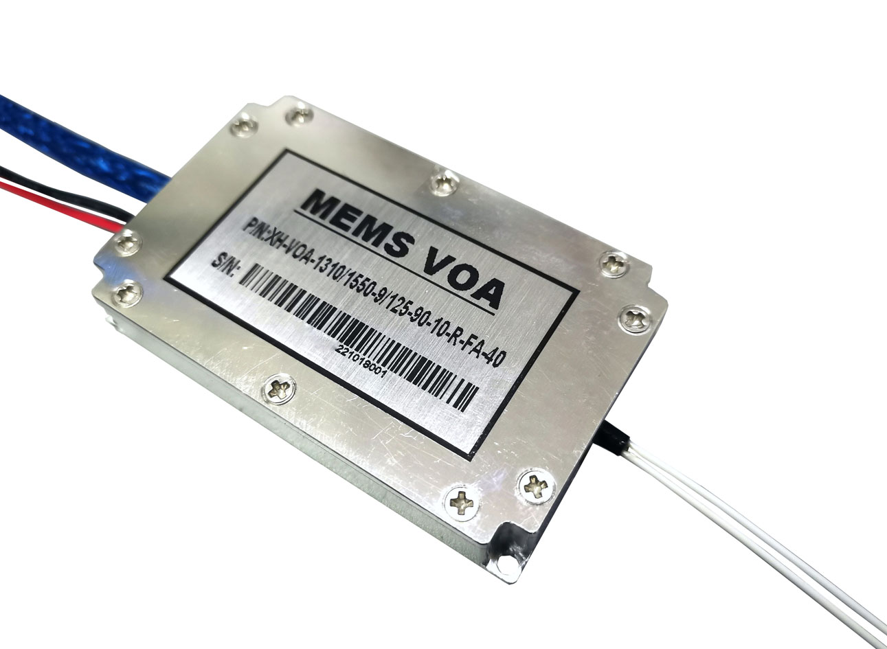
♦ MEMS (Micro-Electro-Mechanical Systems): Employs a miniature electronically controlled mirror to adjust the optical path; features millisecond-level response times and a compact footprint, serving as a core solution for dynamic control in modern communications.
♦ Liquid Crystal/Magneto-optic: Involves no mechanical movement, instead utilizing voltage or magnetic fields to alter light polarization states for attenuation; offers excellent vibration resistance and stability, making it ideal for high-precision scientific research and high-end equipment applications.
3. Four Key Functions of Optical Attenuators
Many people wonder: isn’t a stronger optical signal better? Why attenuate it? In reality, excessive optical power is far more damaging in optical communications than insufficient power!
♦ Protecting optical equipment and preventing burnout: Optical receivers and optical modules have specific maximum optical power ratings (overload thresholds). Long-haul optical modules transmit at very high power levels; if used directly for short-distance patching within a server room, the intense light can instantly destroy the photodetector, rendering the equipment unusable. Attenuators keep input power within the equipment’s normal operating range, serving as the “first line of defense” for the optical circuit.
♦ Balancing power across multiple optical paths: In WDM (Wavelength Division Multiplexing) and multi-stage splitting PON networks, optical power levels can vary drastically between channels and links, often leading to signal overload in some channels and weak signals in others. Attenuators precisely equalize power levels across paths, ensuring balanced and stable signal transmission for all channels.
♦ Essential for equipment testing and calibration: During production-line testing and R&D experiments for optical modules, optical amplifiers, and detectors, it is necessary to simulate optical signals of varying strengths to test key metrics such as sensitivity, overload power, and dynamic range. Attenuators are indispensable tools for these tests.
♦ Suppressing optical reflections and reducing bit errors: High-quality attenuators feature an 8° angled end-face design that significantly reduces optical return loss (back-reflection). This prevents reflected light from interfering with laser operation, thereby eliminating issues such as signal jitter, network bit errors, and link instability.
4. Key Parameters of Optical Attenuators
♦ Attenuation Value (Fundamental Metric): Determines the magnitude of optical power reduction and is the primary criterion for selection. Common fixed values include 5dB, 10dB, 15dB, 20dB, and 30dB (plug-and-play); common adjustable ranges include 0–15dB, 0–30dB, and 0–60dB (dynamic adjustment). Higher values indicate stronger attenuation. Calculation formula: Attenuation (dB) = 10 log₁₀ (Input Optical Power / Output Optical Power).
♦Operating Wavelength: Must match the transmission band of the optical path. The C-band (1530–1565 nm) is most common in communications, compatible with the vast majority of long-haul and WDM equipment. Full-band (1200–1650 nm) models offer greater versatility, supporting O-band and L-band compatibility.
♦ Insertion Loss (IL): Refers to the inherent loss of the attenuator itself, independent of the rated attenuation value. Lower values indicate better performance; high-quality, engineering-grade products feature IL < 0.8 dB, preventing additional loss from interfering with normal link transmission.
♦Return Loss (RL) (Critical Parameter): A key metric for measuring optical reflection interference; higher values indicate lower reflection and greater link stability. The industry standard is ≥45 dB. Excessively low return loss can easily trigger issues such as laser instability, network bit errors, and intermittent link interruptions. For high-speed, long-haul links, APC (Angled Physical Contact) connectors are preferred to significantly improve return loss performance.
♦Attenuation Accuracy and Repeatability: Directly determine the precision of optical path tuning. Standard engineering-grade accuracy is ±0.5 dB, sufficient for routine tuning; high-precision models (±0.1 dB) are required for laboratory and precision testing scenarios. Repeatability reflects long-term device stability; smaller deviations ensure consistent attenuation parameters during repeated use.
♦ Maximum Optical Power Handling: Standard commercial attenuators support optical power up to 500 mW, suitable for typical link tuning. For optical amplifiers and high-power laser paths, specialized high-power attenuators must be used to prevent device overheating, burnout, or failure due to aging.
Although compact in size and simple in structure, the optical attenuator serves as an indispensable guardian of stability within optical communication links.
Comments are closed