


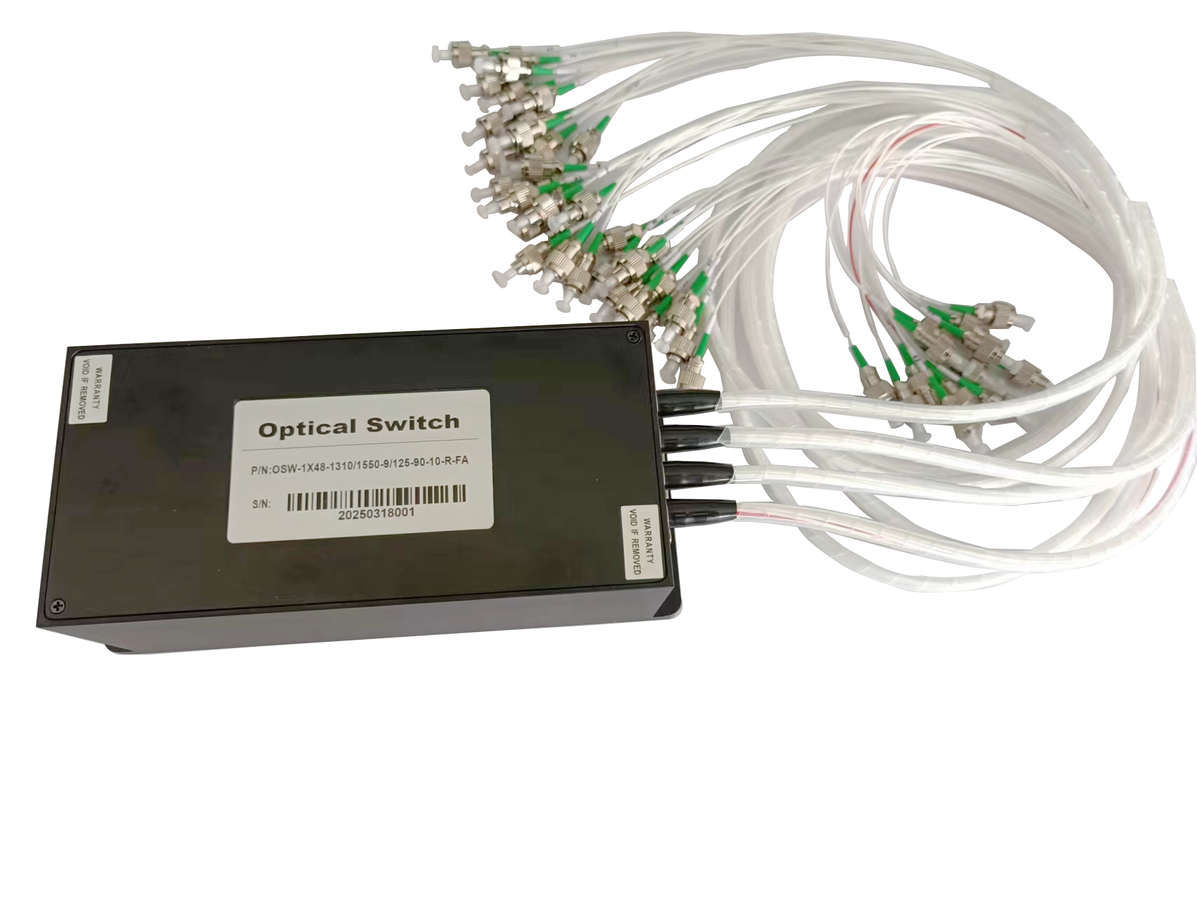
RS232-Controlled 1×48 Mechanical Optical Switch for Automated Fiber Optic Testing
In fiber optic communications, optical component testing, fiber sensing, and laboratory automation, the number of optical channels requiring testing continues to increase. Traditional manual fiber patching and unplugging can no longer meet the growing demand for high testing efficiency, consistency, and automation.
Especially when dozens of optical fibers, optical devices, or channels need to be tested continuously, an automated method for switching optical paths becomes essential.
RS232-controlled 1×48 mechanical optical switch provides a practical and highly integrated solution for multi-channel automated fiber optic testing systems.
What Is a 1×48 Mechanical Optical Switch?
A 1×48 optical switch typically consists of one common input port and 48 output ports.
The input optical signal can be automatically switched to any one of the 48 output channels through electronic control.
Its basic optical path can be described as:
COM → CH1 / CH2 / CH3 / … / CH48
At any given time, the input optical signal is connected to one selected output channel. By sending a control command, the system can automatically switch from one optical path to another.
This configuration is particularly suitable for applications requiring sequential or repeated testing of a large number of optical fibers or devices.
Why Use a 48-Channel Optical Switch for Automated Testing?
In a traditional testing setup, testing 48 optical fibers or devices may require engineers to repeatedly connect and disconnect fiber patch cords.
This manual process can create several challenges:
- Time-consuming operation
- Increased risk of human error
- Repeated connector handling and potential contamination
- Reduced testing consistency
- Difficulty in performing unattended, long-duration testing
With a 1×48 mechanical optical switch, all optical connections can be completed before testing begins.
The PC or automated testing software can then send commands through the RS232 interface to select different optical channels automatically.
A typical testing sequence may look like this:
Send switching command → Switch to the selected channel → Acquire test data → Save the result → Switch to the next channel
This automated process can significantly reduce manual intervention and improve overall testing efficiency.
RS232 Control for Easy System Integration
RS232 is a widely used serial communication interface in laboratory instruments and industrial equipment.
For automated testing systems, RS232 control offers several advantages, including simple communication, good compatibility, and convenient software integration.
The 1×48 optical switch can be connected to:
- PCs
- Automated test platforms
- Industrial computers
- PLC systems
- Optical power measurement systems
- Optical spectrum analyzers
- Custom LabVIEW or Python-based test programs
The testing software can send commands according to a predefined sequence.
For example:
Test CH1 → Test CH2 → Test CH3 → … → Test CH48
After completing the testing of all 48 channels, the system can return to a specified channel or automatically start another testing cycle.
This makes the switch particularly useful for laboratories and production environments that require repeated or continuous testing.
Typical Applications in Multi-Channel Optical Testing
1. Automated Insertion Loss Testing
When multiple optical fibers, fiber assemblies, or optical components need to be tested, each device under test can be connected to one of the 48 output ports.
The automated system can switch between channels and record the test results for each device.
Typical applications include:
- Fiber patch cord testing
- Fiber coupler testing
- WDM testing
- Optical switch testing
- Fiber collimator testing
- Other passive optical component testing
2. Automated Optical Power Monitoring
In multi-channel fiber optic systems, a single optical power meter may need to monitor multiple optical paths.
A 1×48 optical switch allows the measurement system to sequentially select different optical channels and measure the optical power of each one.
For example:
CH1 → Optical Power Measurement → CH2 → Optical Power Measurement → … → CH48
Compared with using multiple optical power meters, this approach can simplify the test setup and reduce equipment requirements.
3. Batch Testing of Optical Devices
During the testing of optical modules or other active optical devices, the system may need to repeatedly measure multiple units.
By connecting different devices to separate channels, the RS232-controlled optical switch can automatically select each device according to the test program.
This approach is suitable for:
- Batch production testing
- Burn-in testing
- Long-term stability testing
- Automated performance testing
4. Fiber Optic Sensing Systems
Fiber optic sensing systems may require the system to access multiple sensing channels sequentially.
1×48 optical switch can automatically select different sensing paths and direct the optical signal to the required channel.
Typical applications include:
- Fiber optic sensor arrays
- Multi-point sensing systems
- Laboratory optical testing platforms
- Multi-channel optical monitoring systems
Advantages of a Mechanical Optical Switch
For multi-channel automated testing, a mechanical optical switch offers a practical solution with several important advantages.
High Channel Density
A single device can provide automatic switching between one common port and 48 output channels, making it suitable for high-density optical testing systems.
Reduced Manual Fiber Handling
Once the optical fibers are connected, the subsequent testing process can be controlled automatically through software, reducing repeated manual handling.
Suitable for Repetitive Testing
For test systems that need to operate continuously for hours or longer, the control software can repeatedly execute predefined channel-switching sequences.
Easy Control and Integration
The RS232 interface allows convenient connection to PCs and automated testing software, making the switch easy to integrate into existing test platforms.
Improved Use of Test Equipment
By automatically switching between optical paths, one measurement instrument can sequentially test multiple channels, potentially reducing the number of instruments required in the test system.
How to Build an Automated Fiber Optic Test System
A typical multi-channel automated fiber optic testing system may include:
Light Source → 1×48 RS232 Optical Switch → Device Under Test → Optical Power Meter / Optical Spectrum Analyzer / Detector
At the same time, a PC communicates with the optical switch through the RS232 interface and controls the measurement instruments.
The automated testing software can follow a sequence such as:
- Initialize the optical switch and test instruments.
- Switch to CH1.
- Wait for the optical path to stabilize.
- Acquire measurement data.
- Save the CH1 test result.
- Switch automatically to CH2.
- Repeat the testing process.
- Continue until CH48 has been tested.
- Generate test data or a test report automatically.
This approach reduces manual intervention and helps create a more standardized and repeatable testing process.
Key Parameters to Consider
When selecting a 1×48 mechanical optical switch for automated fiber optic testing, several specifications should be considered:
- Fiber type: SM, MM, or PM
- Operating wavelength
- Wavelength range
- Insertion loss
- Return loss
- Crosstalk
- Polarization-dependent loss
- Switching time
- Communication interface
- Control protocol
- Fiber connector type
- Bidirectional operation requirements
- Operating lifetime
- Environmental requirements
For polarization-maintaining fiber systems, polarization performance and extinction ratio may also be important considerations.
Since different automated test systems may have different requirements, it is important to confirm the optical and control specifications before selecting the switch.
Moving from Manual Testing to Automation
As the number of optical fibers and devices requiring testing continues to grow, testing efficiency has become an increasingly important factor in both R&D and manufacturing.
An RS232-controlled 1×48 mechanical optical switch can replace repeated manual fiber switching with programmable, automated channel selection.
For applications that require sequential testing of multiple optical fibers, optical components, or optical signal paths, it provides a practical solution for building a more efficient, stable, and standardized automated testing platform.
From multi-channel testing in R&D laboratories to batch testing on production lines and long-term reliability testing, a 1×48 mechanical optical switch can play an important role in automated fiber optic test systems.
Comments are closed